Copyright © 1996 General Motors Corp. 7–15
ASSEMBLY OF TRANSMISSION
NOTE:
The detent spring must be held in alignment over
the selector lever while the 1
3
⁄4 inch bolt is tight-
ened.
(16) Using preset torque wrench J 29612,
tighten the bolts evenly to 8–12 lb ft (11–16 N·m).
b. Filter
(1) Install the sealring onto the straighter end
of the intake tube. Lubricate the sealring with trans-
mission fluid.
CAUTION:
Avoid twisting the intake tube or filter when in-
stalling the filter, intake tube, and sealring. The
sealring may become pinched, cut, or deformed.
An airtight seal must be maintained.
(2) Install the intake tube and sealring (Fig-
ure 7–34).
(3) Install the filter onto the intake tube,
making sure the grommet in the filter fits the intake
pipe snugly (Figure 7–34).
NOTE:
Turn the intake tube until it enters the grommet
squarely.
(4) Retain the filter with bolt 35 (Foldout
12,B) or bolt 42 and washer 43 for the deep pan or bolt
23 for the shallow pan configuration. Tighten the bolt
to 10–15 lb ft (14–20 N·m).
c. Oil Pan
(1) Position the pan gasket on the transmis-
sion housing, aligning its bolt holes with those in the
housing (Figure 7–35).
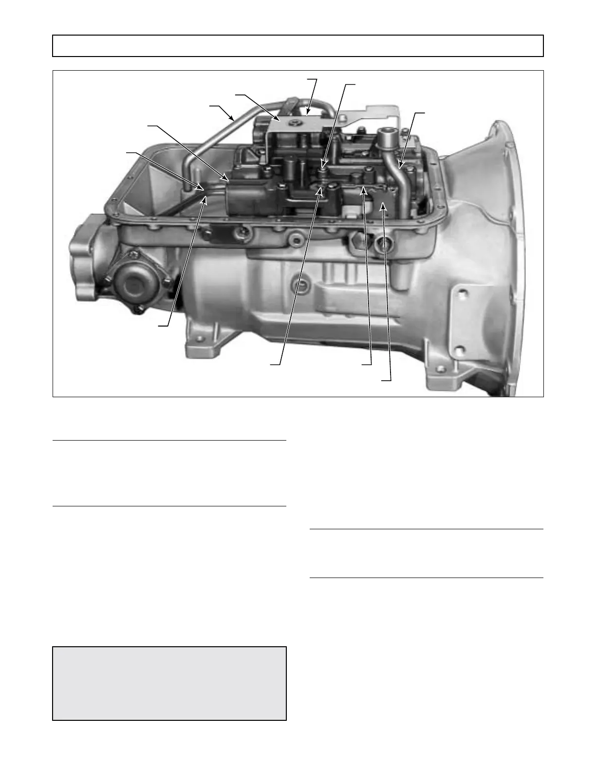
Figure 7–33. Installing Valve Body and Sump Components
BOLT – LATER MODELS (16)
BOLT – EARLIER MODELS (17) OR (18)
FIRST CLUTCH FEED
TUBE BOLTS, 3 in. (2)
INTAKE TUBE
FILTER SPACER
FILTER SCREEN IN
GOVERNOR FEED
TUBE BORE
GOVERNOR
FEED TUBE
GOVERNOR
PRESSURE TUBE
DETENT SPRING
BOLT, 1
3
⁄4 in.
DETENT SPRING
SELECTOR LEVER
FIRST CLUTCH TUBE
(EARLIER MODELS)
H02898
 Loading...


