5–6 Copyright © 1996 General Motors Corp.
AT 500, 1500 SERIES AUTOMATIC TRANSMISSIONS
(7) Remove two hook-type sealrings 38
(Foldout 7,B) and thrust washer 37 from the pump as-
sembly. Refer to Paragraph 6–7 for rebuild of the
pump assembly.
(8) Remove the front support gasket (Figure
5–11 or 5–12).
NOTE:
•
For models without retarder, proceed with Para-
graph 5–3
j
.
•
For models with retarder, skip Paragraph 5–3
j
and proceed with Paragraph 5–3
k
.
j. Removal of Forward Clutch
and Turbine Shaft
(1) Grasp the turbine shaft (Figure 5–11) and
lift out the forward clutch and turbine shaft assembly.
(2) Remove thrust washer 33 (Foldout 8)
from the rear of the forward clutch assembly. Refer to
Paragraph 6–9 for rebuild of the forward clutch and
turbine shaft assembly.
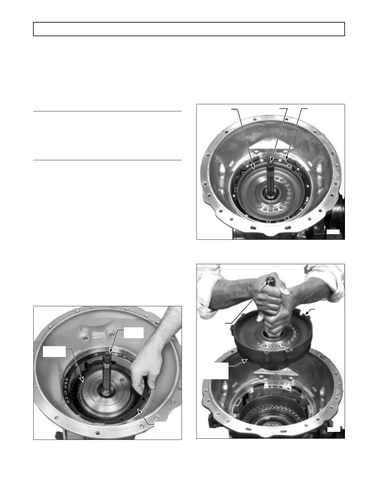
k. Removal of Retarder Components,
Forward Clutch and Turbine Shaft
(1) Grasp the turbine shaft 14 and lift out the
forward clutch and turbine shaft assembly (Figure 5–13).
Figure 5–11. Removing Front Support Gasket
(Models Without Retarder)
(2) Lift the front stator from the forward
clutch assembly (Figure 5–13).
(3) Remove thrust washer 31 (Foldout 8)
from the rear of the forward clutch assembly. Refer to
Paragraph 6–8 for rebuild of the forward clutch and
turbine shaft assembly.
Figure 5–12. Removing Front Support Gasket
(Models With Retarder)
Figure 5–13. Removing Forward Clutch and Turbine
Shaft Assembly and Front Stator (Models With Retarder)
H02901
GASKET
TURBINE
SHAFT
FORWARD
CLUTCH
H03016
RETARDER
FRONT
STATOR
TURBINE SHAFT FRONT
SUPPORT
GASKET
H03017
RETARDER
FRONT
STATOR
TURBINE
SHAFT
FORWARD
CLUTCH
ASSEMBLY
 Loading...


