6–8 Copyright © 1996 General Motors Corp.
AT 500, 1500 SERIES AUTOMATIC TRANSMISSIONS
consisting of two governor weight pins and the cover
gasket is available.
(2) Follow the directions furnished with the
kit to disassemble the governor.
b. Assembly
(Foldout 12,A)
(1) Assemble the governor as outlined in the
directions furnished with the governor service kit.
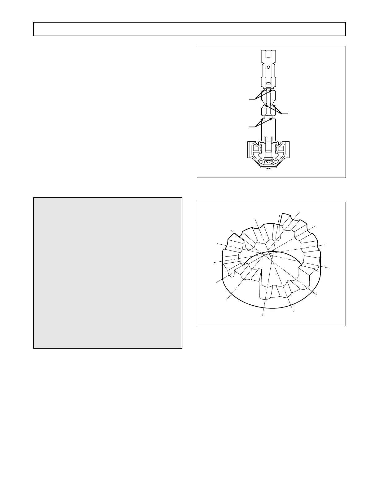
(2) Check the governor port openings as out-
lined in the kit instructions. Refer to Figure 6–17.
6–6. MAIN CONTROL VALVE BODY
a. Disassembly
(Foldout 11)
(1) Remove manual selector valve 53 from
control valve body 11.
(2) Remove three bolts 3 from modulator
valve body 10. Remove the valve body and separator
plate 2.
(3) Remove priority valve 45, spring 44, and
valve stop 43 from valve body 11.
(4) Compress adjusting ring 4 or 82 and re-
move retainer pin 9.
Figure 6–17. Governor Assembly — Showing
Port Openings
Figure 6–18. Step Numbers for Recording the Positions
of Adjusting Rings
(5) For some models, remove adjusting ring
82, spring 7, modulator valve 81, and actuating rod 80.
For other models, remove adjusting ring 4, stop 5,
spring washer 6, spring 7, and modulator valve 8.
(6) Remove nine bolts 35 (eight, some mod-
els) from trimmer cover 34. Remove trimmer cover 34.
(7) Remove from the bores in valve body
11, spring 14, stop 15, plug 13, and third clutch trim-
mer valve 12; springs 18 and 19 (if present), stop 20,
plug 17, and first clutch trimmer valve 16; springs 23
and 24 (if present), stop 25, plug 22, and second
CAUTION:
•
Before removing retainer pins 9, 52, 59, 65,
and 71, record the positions of adjusting rings
4 or 82, 51, 58, 64, and 70 (Figure 6–18). To
retain the original calibration of the valve as-
sembly, the adjusting rings must be rein-
stalled in the same positions as when
removed. Adjusting rings are spring-loaded.
•
The main control valve body assembly con-
tains springs and other parts, some of which
are similar and can be mistakenly inter-
changed. If parts are not reinstalled in the
same locations from which they were re-
moved, the calibration of valve body func-
tions will be lost. Tag each part at removal
with its item number in Foldout 11 and utilize
valve body parts tray set J 33163 to simplify
correct reassembly of the valve body compo-
nents.
GOVERNOR FEED
(Must open 0.020 in.
(0.51 mm) min)
GOVERNOR
PRESSURE
PORTS
EXHAUST PORTS
(Must open 0.020 in.
(0.51 mm) min)
V02308
 Loading...


