Copyright © 1996 General Motors Corp. 6–25
REBUILD OF SUBASSEMBLIES
(12) Place PTO gear 32 onto the forward
clutch housing. Be sure the chamfer on the inside di-
ameter of the PTO gear is facing downward.
(13) Compress snapring 31 into the clutch
housing and install the PTO gear. Be sure the gear is
positioned so that the snapring expands into the gear.
Proceed to Step (17).
(14) For earlier models, install wave-type
snapring 5 (Foldout 8) onto forward clutch housing 9.
Be sure the tips of the snapring face the PTO gear.
(15) Install PTO drive gear 4 (flat side toward
front of transmission), from the turbine shaft side, un-
til it is firmly seated against snapring 5.
(16) Install snapring 3 onto housing 9 to se-
cure gear 4.
(17) Install hook-type sealring 2 onto the tur-
bine shaft.
(18) For models with retarder, install two
hook-type sealrings 12 onto forward clutch housing 14.
6–11. RETARDER HOUSING ASSEMBLY
a. Disassembly
(1) Place retarder housing assembly 34
(Foldout 8) on the work table with the screw side fac-
ing upward.
(2) Remove four screws 37.
(3) Separate rear stator 35 from retarder
housing 36.
(4) Visually inspect that all fluid passage
holes are clean and free of debris.
b. Assembly
(1) Place rear stator 35 in place in retarder
housing 36, aligning the bolt holes. Start one screw 37
to establish alignment.
(2) Install the remaining three screws 37.
Tighten all four screws to 10–12 lb ft (14–16 N·m).
6–12. FOURTH CLUTCH ASSEMBLY
a. Disassembly (Foldout 9,A)
(1) Place the fourth clutch on the work table,
with snapring 1 upward. Remove snapring 1, back-
plate 2, five internal-splined clutch plates 3, and five
external-tanged clutch plates 4.
(2) Place fourth clutch housing assembly 11
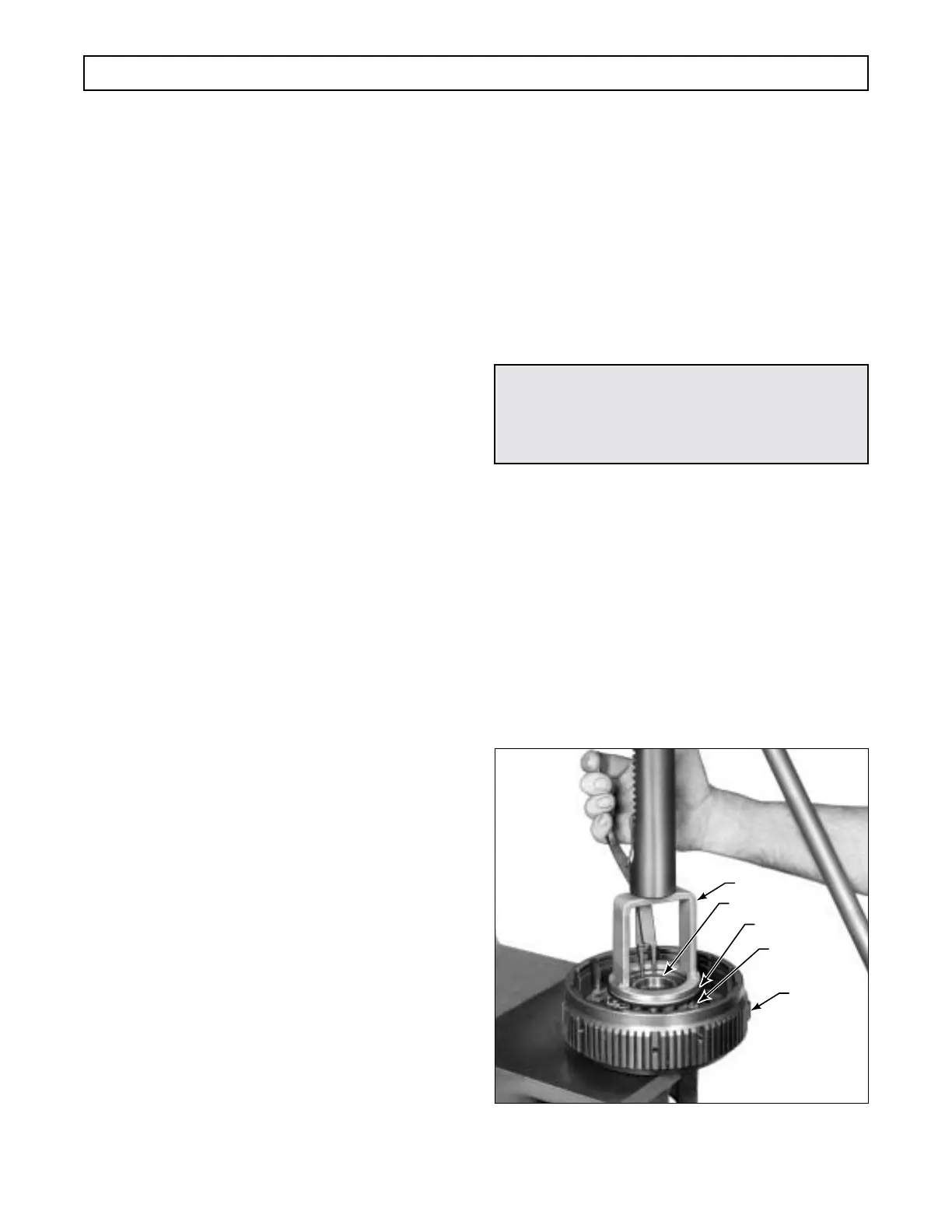
in a press (Figure 6–43).
(3) Using spring compressor J 23616, com-
press piston return spring retainer 6 and remove
snapring 5 and spring retainer 6.
(4) Remove sixteen piston return springs 7
and remove fourth clutch piston 8.
(5) Remove sealring 9 from the OD of pis-
ton 8. Remove sealring 10 from the ID of piston 8.
Check the sealring groove thoroughly for burrs and
rough spots.
Figure 6–43. Removing (or Installing) Fourth Clutch
Spring Retainer Snapring
CAUTION:
When removing the fourth clutch snapring, do
not allow the spring retainer to catch in the
snapring groove.
H02950
J 23616
HOUSING
SPRING (16)
RETAINER
SNAPRING
 Loading...


