6–24 Copyright © 1996 General Motors Corp.
AT 500, 1500 SERIES AUTOMATIC TRANSMISSIONS
(4) Using compressor tool J 23616, com-
press the spring retainer until it clears the snapring
groove in the housing hub (Figure 6–37). Install
snapring 22 (Foldout 8) into the groove in the hub in
the clutch housing assembly. Release the press and re-
move the clutch housing assembly.
(5) Install the flat bearing race onto the hub
of the forward clutch housing (Figure 6–41). Install
the thrust needle bearing and the lipped bearing race
so that it encloses the bearing. Retain the bearing and
races with oil-soluble grease.
(6) Install the forward clutch hub into the
clutch housing (Figure 6–42).
NOTE:
• For models with a wave plate next to piston 19
(Foldout 8), proceed with Step (7).
• For models not equipped with a wave plate next to
piston 19, skip Step (7) and proceed with Step (8).
(7) Install the clutch pack established in
Paragraph 6–17b(3). Begin by placing the wave plate
next to piston 19 (Foldout 8). Then alternately install
five internal-splined and the remaining four external-
tanged clutch plates into the forward clutch housing
assembly. Skip Step (8) and proceed with Step (9).
Figure 6–41. Installing Forward Clutch Thrust Bearing
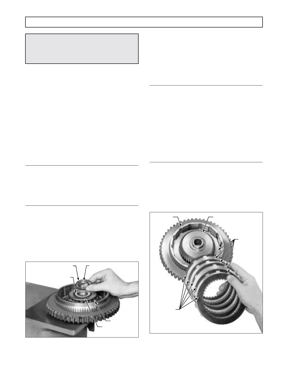
(8) Beginning with an external-tanged clutch
plate, install the clutch pack established in Paragraph
6–9c(6) or 6–17b(3) (Figure 6–42).
(9) Install the fourth clutch drive hub (Figure
6–39) into the housing assembly and secure the hub
with snapring 30 (Foldout 8).
NOTE:
• For assembly of the PTO gear for later models
do Steps (10) through (13) and Step (17).
• For assembly of the PTO gear for earlier models,
skip Steps (10) through (13), and do Steps (14)
through (17).
• For non-retarder models that do not include a
PTO gear, skip Steps (10) through (16) and do
Step (17) only.
• For retarder models, skip Steps (10) through
(16) and do Steps (17) and (18).
(10) For later models, place forward clutch
housing and turbine assembly 7 (Foldout 8) on the
work table, shaft downward.
(11) Install snapring 31 into the snapring
groove in forward clutch housing 9.
Figure 6–42. Installing Forward Clutch Plates
(Models Without Wave Plate)
CAUTION:
When installing the forward clutch snapring, do
not allow the spring retainer to catch in the
snapring groove.
H02948
SPRING (16)
SPRING RETAINER
BEARING RACE (FLAT)
BEARING RACE (LIPPED)
THRUST BEARING
H02949
EXTERNAL-
TANGED
PLATE (5)
INTERNAL-
SPLINED
PLATE (5)
CLUTCH
HOUSING
CLUTCH HUB
 Loading...


