6–26 Copyright © 1996 General Motors Corp.
AT 500, 1500 SERIES AUTOMATIC TRANSMISSIONS
NOTE:
Earlier model transmissions use a piston seal on
fourth clutch housing 13. If present, discard the
housing seal. A fourth clutch housing seal should
not be used during assembly. Use only the two seals
on the piston.
(6) Refer to Paragraph 4–5p and Figure 6–45
for housing check ball specifications. Remove the ball
from the fourth clutch housing only if replacement is
necessary. If necessary, clear the bore of the staked
metal and remove the ball.
b. Checking Clutch Pack Clearance
NOTE:
• Two methods of establishing proper clutch clear-
ance are explained and illustrated. The first
method, Steps (1) through (6), is by direct mea-
surement using a go/no-go gauge. The second
method is by stack dimension computation
(Paragraph 6–17). This method may be more
convenient when assembly line overhaul practic-
es are used.
• If piston 8 must be replaced, be sure that the
identification (A, B, C, EF, E, or DE) on the new
piston is the same as that on the old piston.
(1) Install the piston, without sealrings, into
the clutch housing assembly until the piston bottoms
against the housing.
(2) Beginning with an external-tanged plate,
alternately install five external-tanged clutch plates 4
(Foldout 9,A) and five internal-splined clutch plates 3
onto piston 8.
(3) Install clutch backplate 2, flat side first,
onto the last clutch plate 3 installed. Install snapring 1
into housing 13.
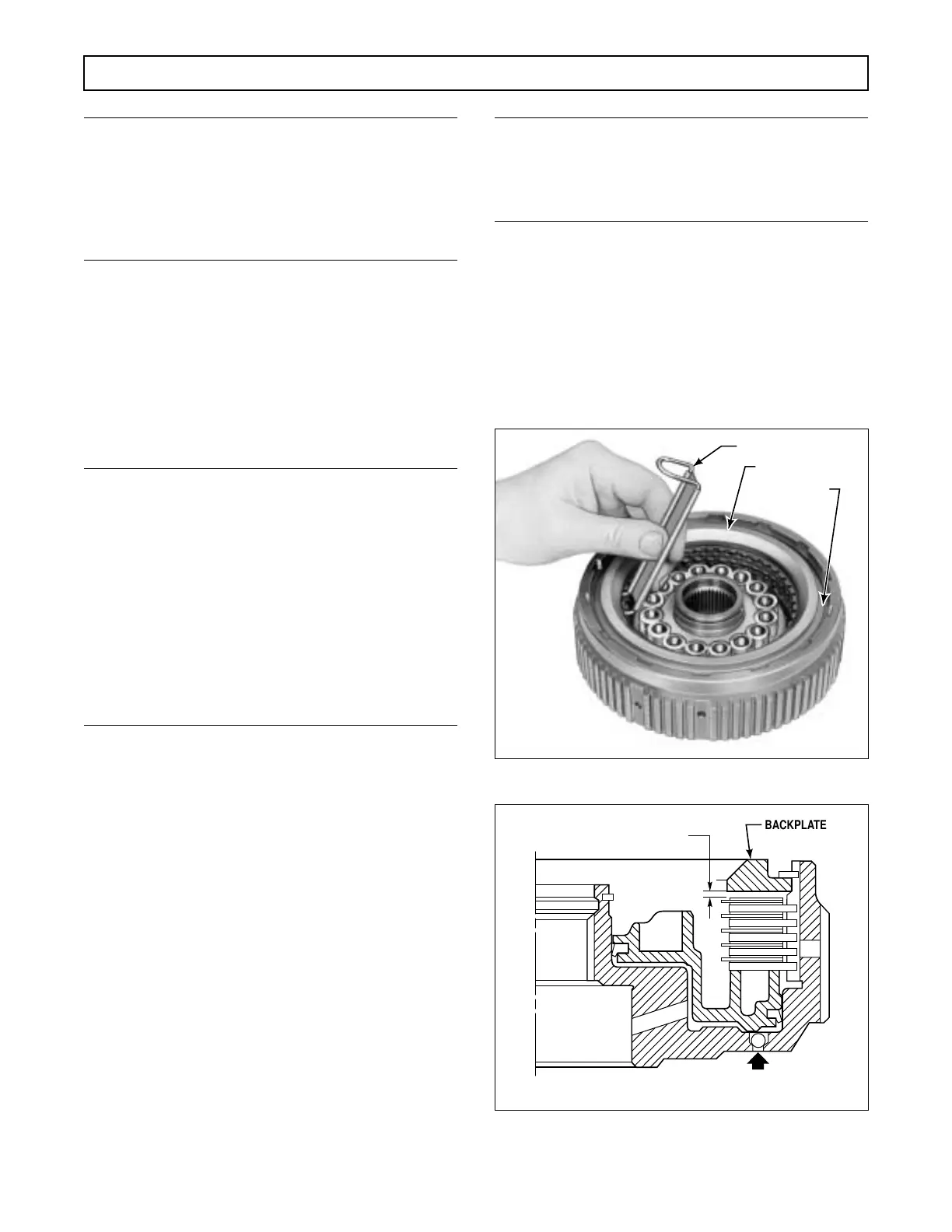
(4) While holding backplate 2 firmly against
snapring 1, use clutch clearance gauge J 23619-01 to
measure the clearance between the backplate and the
clutch plate (Figure 6–44). The smaller end of the
gauge must insert between the backplate and the first
clutch plate. The larger end must not.
NOTE:
If the J 23619-01 gauge is not available, measure the
clearance between the backplate and the first clutch
plate (Figure 6–45).
(5) If the clutch running clearance is not
within the specified limits, remove snapring 1, back-
plate 2, and clutch plates 3 and 4. Replace clutch
plates 3 and 4 with new plates or replace piston, as re-
quired, to establish the proper running clearance. Re-
fer to wear limits, Section 8, to determine the plates
which should be replaced.
Figure 6–44. Checking Fourth Clutch Clearance
Figure 6–45. Fourth Clutch Clearance Check Point
H02951
J 23619-01
BACKPLATE
FOURTH
CLUTCH
ASSEMBLY
V02952
Minimum Axial Movement
0.040 in. (1.02 mm)
Check clearance here
0.0765 – 0.1265 in.
(1.944 – 3.213 mm)
 Loading...


