6–22 Copyright © 1996 General Motors Corp.
AT 500, 1500 SERIES AUTOMATIC TRANSMISSIONS
(17) Remove spring retainer 21 (Foldout 8)
and sixteen clutch springs 20.
(18) Remove forward clutch piston 19 from
the clutch housing. If necessary, turn the clutch hous-
ing over and “bump” the piston from the housing.
(19) Remove piston outer sealring 18 and pis-
ton inner sealring 17. Inspect ball 10 or 15 to make
sure it moves freely in the housing. If the piston is be-
ing replaced, be sure the new piston has the same letter
identification (A, B, C, EF, E, or DE) that was stamped
on the old piston.
(20) Refer to Paragraph 4–5p and Figure 6–40
for housing check ball specifications. Remove ball 10
or 15 (Foldout 8) from the forward clutch housing only
if replacement is necessary. If necessary, clear the bore
of staked metal and remove the ball.
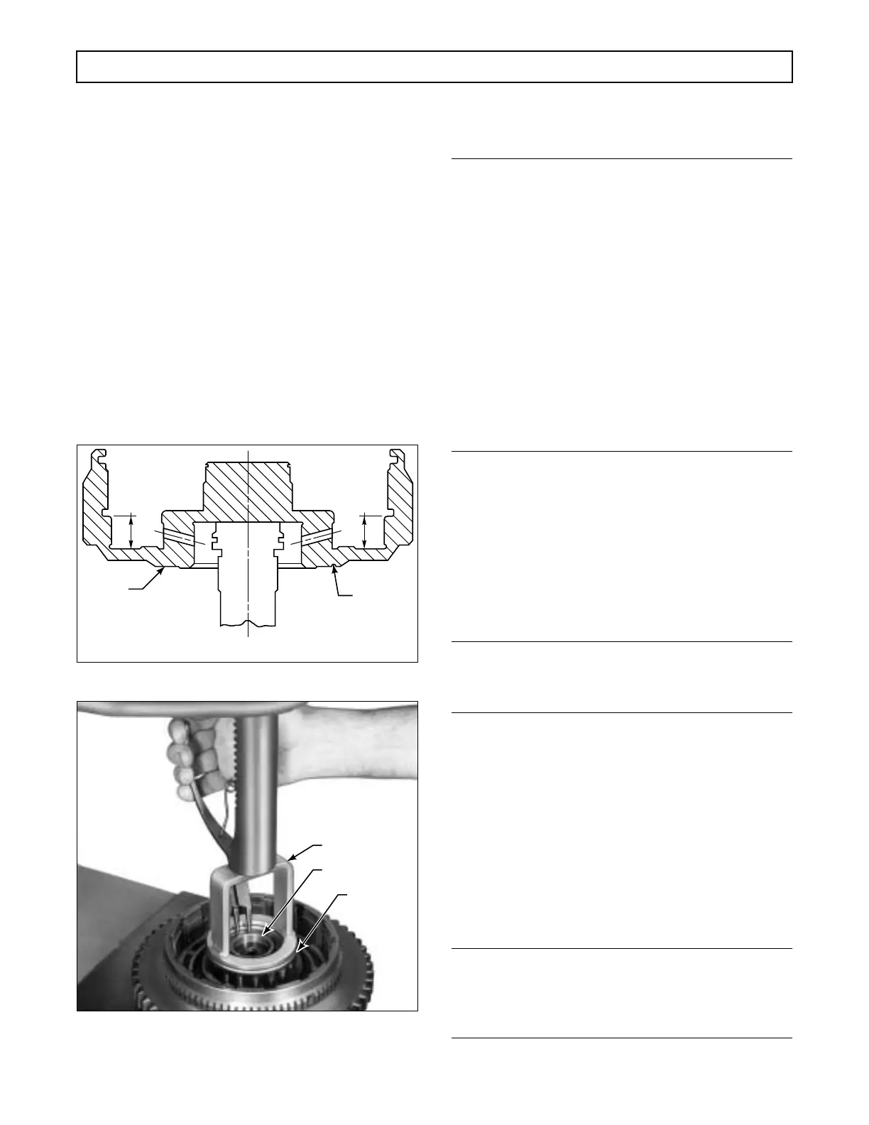
Figure 6–36. Forward Clutch Housing Identification
Figure 6–37. Removing (or Installing) Forward Clutch
Spring Retainer Snapring
b. Checking Clutch Pack Clearance
(Models Without Wave Plate)
NOTE:
Two methods of establishing proper clutch clear-
ance are explained and illustrated. The first meth-
od, Steps (1) through (6), is by direct measurement
using a go/no-go gauge and is only to be used for
checking the forward clutch in models NOT
equipped with a wave plate next to piston 19 (Fold-
out 8). The second method is by stack dimension
computation (Paragraph 6–16). This method may
be more convenient when assembly line overhaul
practices are used. THE STACK DIMENSION
METHOD MUST ALSO BE USED FOR CHECK-
ING THE FORWARD CLUTCH IN MODELS
EQUIPPED WITH A WAVE PLATE NEXT TO
PISTON 19.
(1) Install the piston, without sealrings, into
forward clutch housing 8 (Foldout 6,A) until the piston
bottoms against the housing.
(2) Beginning with an external-tanged plate,
alternately install five external-tanged clutch plates 27
and five internal-splined clutch plates 28 into the for-
ward clutch housing assembly.
NOTE:
Before installing the fourth clutch drive hub, refer
to Paragraph 6–9b and to Figure 6–38.
(3) Install the fourth clutch drive hub (Figure
6–38) into the housing assembly, engaging the tangs in
the slots. Install snapring 30 (Foldout 8) into the hous-
ing assembly.
(4) While holding clutch drive hub 29 firmly
against snapring 30, use clearance gauge J 23619-01
to measure the clutch running clearance (Figure 6–39).
The smaller end of the gauge must insert between the
hub and the first plate. The larger end must not.
NOTE:
If the J 23619-01 gauge is not available, measure the
clearance between the hub and the first plate (Fig-
ure 6–40).
LATER
HOUSING WITH
WAVE PLATE
EARLIER
HOUSING WITHOUT
WAVE PLATE
.560 in.
(14.22 mm)
.641 in.
(16.28 mm)
V01305
GROOVE
NO
GROOVE
H02943
J 23616
SNAPRING
RETAINER
 Loading...


