Copyright © 1996 General Motors Corp. 6–21
REBUILD OF SUBASSEMBLIES
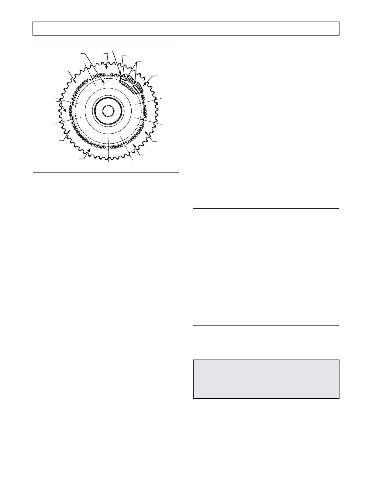
Figure 6–35. Removing PTO Gear From
Forward Clutch Housing
(Later Models Without Retarder)
(5) Using the screwdriver in the openings
(omitted splines) as required to depress the snapring,
place steel strips in housing spline roots as necessary
to hold the snapring inward. Work from the strips first
installed to a point opposite the gap.
(6) Use as many strips as required (8 should
be sufficient) and place them at positions that will hold
the snapring entirely clear of the PTO gear splines.
(7) When the snapring clears the PTO gear
splines, light can be seen through all spaces (except
those holding steel strips) between PTO gear spline
tips and housing spline roots. Remove the gear.
(8) For models with retarder, remove two
hook-type sealrings 12 (Foldout 8) from forward
clutch housing 14.
(9) Remove hook-type sealring 2 (Foldout 8)
from the turbine shaft. Turn the assembly over.
(10) Using a screwdriver, remove snapring 30
from the forward clutch housing. Remove fourth
clutch drive hub 29 from the housing.
(11) Remove forward clutch hub 26 from the
housing.
(12) Inspect forward clutch hub 26 closely on
high mileage transmission units down for overhaul.
Over an extended period of operation, a wear pattern
at the internal spline of the hub may occur. This wear
ring, the result of contact with the transmission main
shaft, is so uniform in shape that it is often overlooked.
Replace this hub where this condition exists. In most
instances, wear of adjacent thrust washers should alert
you to inspect the forward clutch hub for abnormal
wear. Although the transmission may be functioning
properly prior to overhaul, the clutch hub should be re-
placed when wear exists. Reuse of a distressed hub
with new washers will accelerate washer wear and will
not duplicate the original durability and service life.
(13) Remove thrust bearing race 25, thrust
needle bearing 24, and thrust bearing race 23 from the
hub of the forward clutch housing.
(14) Remove five external-tanged clutch
plates 27 and five internal-splined clutch plates 28
from the clutch housing.
NOTE:
• Later models have a wave plate in the forward
clutch next to piston 19 (Foldout 8) which im-
proves the neutral-to-range shift quality. A kit is
available that contains parts required to make
this change. Be sure to confirm all interchange-
ability factors by referring to Parts Catalog
SA1235 or SA2126. Both forward- and fourth-
clutch assemblies have various part numbers af-
fected by this upgrade. Refer also to the latest
version of Service Information Letter 3-TR-93.
• Models that have the wave plate in the forward
clutch assembly use a clutch housing marked
with an identification groove (Figure 6–36).
(15) Place the forward clutch assembly in a
press with the spring retainer upward (Figure 6–37).
(16) Place compressor tool J 23616 on the
spring retainer (Figure 6–37). Compress the retainer
until the snapring is free. Using snapring pliers, re-
move the snapring. Release the press and remove the
assembly.
L02942
FORWARD
CLUTCH HOUSING
PTO
GEAR
SHIM 2
SHIM 1
SHIM 3
SHIM 5
SHIM 7
SHIM 8
SHIM 6
SHIM 4
SNAPRING
SNAPRING
GAP
CAUTION:
When removing the forward clutch snapring, do
not allow the spring retainer to catch in the
snapring groove.
 Loading...


