6–20 Copyright © 1996 General Motors Corp.
AT 500, 1500 SERIES AUTOMATIC TRANSMISSIONS
(14) Install front support assembly 16 onto
pump body assembly 5, aligning the bolt holes.
(15) Install six (eight, some models)
5
⁄16-18 x
1 inch bolts 11 (Foldout 7,B) and new rubber coated
washers 12 into the pump side of the oil pump assem-
bly. Tighten the bolts finger tight.
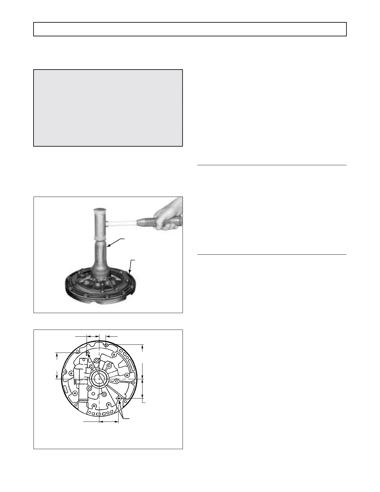
Figure 6–33. Installing Oil Pump Seal
Figure 6–34. Rework Dimensions for Front Support
(16) Install bolts 28 and 29 as were removed.
(For different models, the length may differ).
(17) Tighten all the
5
⁄16-18 bolts to 15–20 lb ft
(20–27 N
.
m).
(18) Lubricate and install sealring 13 onto the
outer diameter of front support 21.
6–10. FORWARD CLUTCH AND
TURBINE SHAFT ASSEMBLY
a. Disassembly
NOTE:
• For earlier models with PTO gear and without
retarder, proceed with Step (1).
• For later models with PTO gear and without re-
tarder, skip Step (1) and proceed with Step (2)
• For models without PTO gear and without re-
tarder, skip Steps (1) through (8) and proceed
with Step (9).
• For models with retarder, skip Steps (1) through
(7) and proceed with Step (8).
(1) For earlier models with PTO gear and
without retarder, place forward clutch and turbine
shaft assembly 7 (Foldout 8) on the work table, with
the shaft upward. Using a screwdriver, remove
snapring 3 that secures PTO drive gear 4 to forward
clutch housing 9. Remove gear 4 and snapring 5. Skip
Steps (2) through (7) and proceed with Step (8).
(2) For later models with PTO gear and
without retarder, locate the snapring gap by looking
between the tips of the PTO gear internal splines and
the roots of the housing splines. Light can be seen in
the gap area.
(3) At the opening (omitted housing spline)
closest to the snapring gap, insert a small screwdriver
and push the snapring toward the housing until a
5
⁄64 x
0.020 inch (2 x 0.5 mm) steel strip, 2 to 3 inches (50–75
mm) long can be inserted in the root of the housing
spline nearest the snapring gap (Figure 6–35).
(4) Repeat Step (3) at the opposite side of
the snapring gap.
CAUTION:
Because of transmission fluid leakage, a six-bolt
support should never be used with an eight-bolt
pump body. However, the six-bolt support may
be modified by tapping two additional holes (Fig-
ure 6–34). Any other combination of parts (6-
hole support with 6-hole body, 8-hole support
with 8-hole body, or 8-hole support with 6-hole
body) is acceptable without modification.
H02940
PUMP BODY
J 21359-A, AT 500 SERIES
(J 39757, AT 1500 SERIES)
L02941
Drill and tap to 0.3125-18
UNC-2B two (2) places,
locate within 0.010 in.
(0.25 mm) radius of the
true position given
3.740 in.
(94.99 mm)
5.036 in.
(127.91 mm)
2.900 in.
(73.66 mm)
1.760 in.
(44.70 mm)
2.920 in.
(74.17 mm)
0.980 in.
(24.89 mm)
REAR VIEW
 Loading...


