Copyright © 1996 General Motors Corp. 6–19
REBUILD OF SUBASSEMBLIES
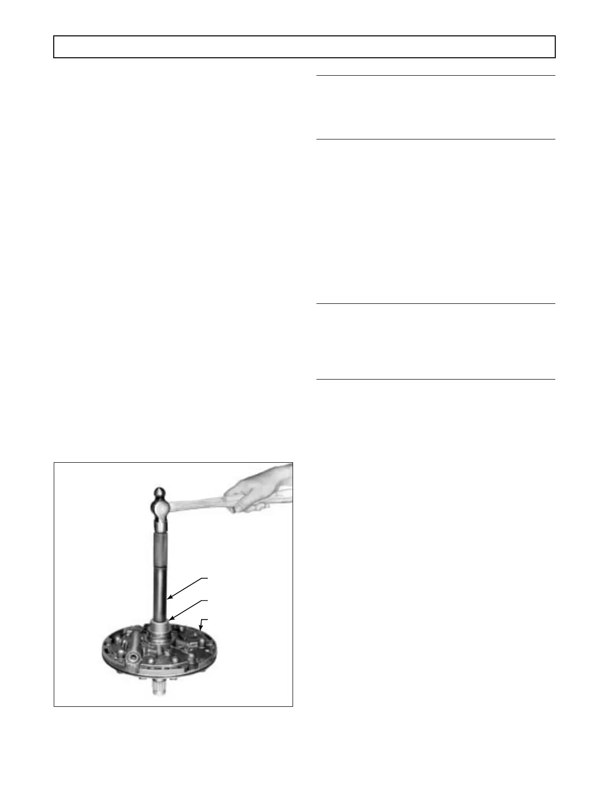
(1) For models without lockup, if roller bear-
ing 23 was removed, using installer J 23615, press on
the lettered end of the new bearing to a depth of
0.595–0.615 inch (15.11–15.62 mm) from the end of
the shaft (Figure 6–32).
(2) Install valve plug 14 (earlier models) into
the main pressure regulator valve bore of front support
21. Install pin 15 (earlier models) into the pump body
side of front support 21. Skip Step (3) and proceed
with Step (4).
(3) For models with lockup, if roller bearing
23 was removed, using installer J 39794, press on the
lettered end of the new bearing to a depth of 0.625–
0.635 inch (15.88–16.12 mm) from the end of the
shaft.
(4) Install main-pressure regulator valve 27,
smaller end first, into its valve bore.
(5) Into the same bore, install valve spring
26 and spring stop 25 (smaller end first).
(6) Install main-pressure regulator valve in-
staller tool J 24787 (Figure 6–24). Restrain spring stop
25 (Foldout 7,B) and install snapring 24, flat side out-
ward. Remove the tool from the assembly.
Figure 6–32. Installing Stator Shaft Rear Bearing
(Models without Lockup)
NOTE:
• For models without lockup, skip Step (7) and
proceed with Step (8).
• For models with lockup, proceed with Step (7).
(7) For models with lockup, install lockup
valve 30 (Foldout 7,B), smaller end first, into pump as-
sembly 16. Into the same bore install spring 31 and
stop 32. Restrain stop 32 and install pin 33 through the
machined side of the front support.
(8) If either plug 20 or 22 was removed, in-
stall a new plug. Press plug 20 into the support to a
depth of flush to 0.010 inch (0.25 mm) below the sur-
face. Press plug 22 to the shoulder in the support.
NOTE:
• For models without lockup, proceed with
Step (9).
• For models with lockup, skip Steps (9) and (10),
and proceed with Step (11).
(9) For models without lockup, if bushing 7
was removed, install a new bushing. The split in the
bushing must be located in an area of the bore that can
completely support it. Use installer tool J 25356 to
press the bushing into the front of the pump body to a
height of 0.010–0.020 inch (0.25–0.51 mm) above the
surface.
(10) Using special installer tool J 21359-A,
install oil seal 3, with the lip facing inward (Figure
6–33). Skip Steps (11) and (12) and proceed with
Step (13).
(11) For models with lockup, if bushing 7 was
removed, install a new bushing. The split in the bush-
ing must be located in an area of the bore that can
completely support it. Use installer tool J 39739 to
press the bushing into the front of the pump body to a
depth of flush to 0.398 inch (10.11 mm).
(12) Using special installer tool J 39757, in-
stall oil seal 3 with the lip facing inward (Figure 6–33).
(13) Lubricate and install sealring 4 (Foldout
7,B) onto pump body 8. Lubricate and install driven
gear 9 and drive gear 10.
H02939
PUMP ASSEMBLY
J 23615
J 8092
 Loading...


