3–18 Copyright © 1996 General Motors Corp.
AT 500, 1500 SERIES AUTOMATIC TRANSMISSIONS
(5) If the transmission was prepared for stor-
age with transmission fluid, it is not necessary to drain
and refill the transmission with new transmission fluid.
Check for proper fluid level as specified in Paragraph
3–5. Add or drain fluid as required to obtain the proper
level.
3–16. REPLACEMENT OF COMPONENTS
WHILE TRANSMISSION IS IN THE
VEHICLE CHASSIS
a. Replacement of Selector Shaft Seal
(Foldout 12,B)
(1) Remove control linkage from selector
shaft 60. Place seal remover J 26401 over the end of
the selector shaft. Screw the remover into seal 61 suffi-
ciently to cause engagement. Then, using a wrench,
tighten the screw in the remover to draw the seal from
the bore.
(2) Clean the housing bore before installing
a new seal. Refer to Paragraph 4–6f for seal prepara-
tion. Install the seal, lip first, onto the selector shaft.
Using seal installer J 26282, install the seal into the
housing. The seal is positioned satisfactorily when its
outer surface is clear of the lead chamfer in the bore.
(3) Install and adjust the control linkage as
outlined in Paragraph 3–12a.
b. Removal of Output Flange, Output Seal
(1) Disconnect the vehicle drive shaft from
the transmission output shaft.
(2) Remove the flange retaining bolt,
washer, and flange retainer washer. Discard the bolt.
(3) Remove the transmission output flange
from the output shaft.
(4) Remove the seal from the rear of the
transmission housing. Do not damage the seal bore.
c. Removal of Output Shaft Bearing
(Foldout 12,B)
(1) Remove internal snapring 5 from the rear
of the transmission housing.
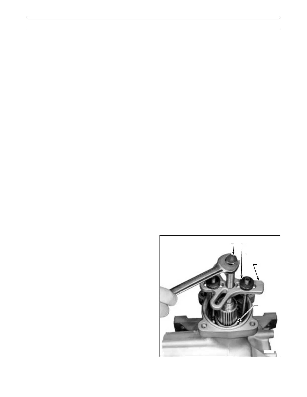
(2) To remove output shaft bearing 4, first
count the number of balls in the bearing (Figure 3–8). If
the bearing has nine balls, select J 38086-1 puller legs
(three required). If the bearing has ten balls, select
J 24463-2 puller legs (two required). Assemble the se-
lected legs with puller body J 24420-B and bolt J 24463.
Engage each puller leg into the bearing by placing the
foot of the leg between two bearing balls. Then twist the
leg so that the foot is forced under the bearing races. Ad-
just the center screw and each of the leg nuts until puller
body J 24420-B is perpendicular to the rear face of the
transmission housing (Figure 3–8). Tighten the center
screw and remove the output bearing.
d. Removal of Speedometer Drive Gear or
Speed Sensor Wheel and Selective Spacer (Foldout
12,B). Remove selective spacer 3 and speedometer
drive gear 2 or speed sensor wheel 9 from the output
shaft. Note the number of grooves on selective spacer
3 for accurate replacement.
e. Installation of Speedometer Drive Gear or
Speed Sensor Wheel and Selective Spacer
(Foldout 12,B)
(1) Install speedometer drive gear 2 or speed
sensor wheel 9 onto the output shaft.
(2) Check selective spacer 3 for damage. If
replacement is required, select a spacer with the same
number of external grooves as the one it replaced. If
spacer identification is impossible, refer to Paragraph
7-6a for replacement procedures.
(3) Install selective spacer 3 onto the output
shaft.
Figure 3–8. Removing Ten-Ball Bearing
from Output Shaft
H02885
BEARING
J 24420-B
J 24463
J 38086-1
(9 BALLS)
J 24463-2
(10 BALLS)
 Loading...


