6–34 Copyright © 1996 General Motors Corp.
AT 500, 1500 SERIES AUTOMATIC TRANSMISSIONS
a. Inspection
(1) Visually inspect the planetary carrier as-
sembly for evidence of excessive wear, indications of
overheating, damage, or heavy metal contamination.
(2) Check the end play of the planetary
carrier pinions. With the washer held flat, insert a
feeler gauge between the carrier and thrust washer.
End play must be within 0.008–0.031 inch (0.20–
0.79 mm).
NOTE:
• Do not disassemble the carrier assembly unless
parts replacement is necessary. Failure of one pin-
ion requires replacement of the entire matched
pinion gear set, pinion pins, and bearings.
• Depending upon the amount of labor (machining
the bushing), time, part replacement, and extent
of rework, complete replacement of the assembly
may be more practical.
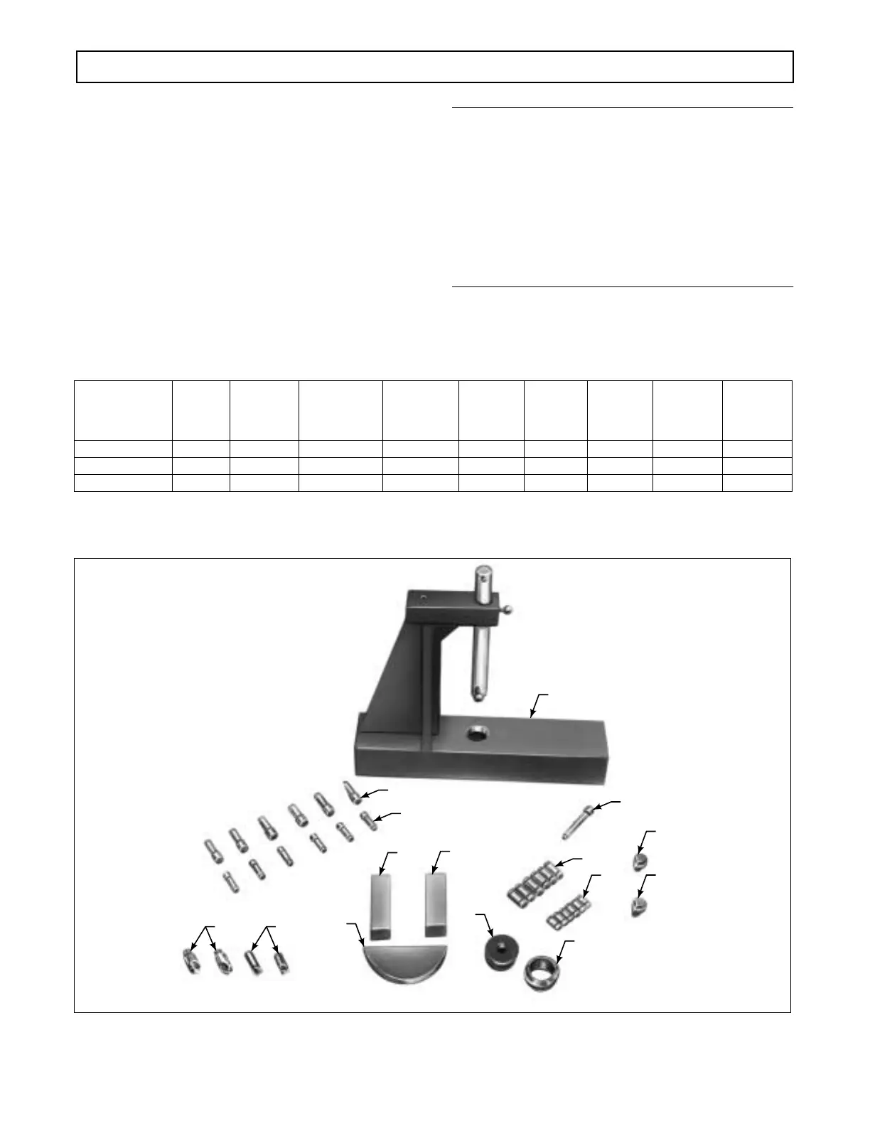
Planetary Carrier Assembly Rebuild Tool Chart
Note — All tools in this chart have a basic number (J 25587) and a suffix. Only the suffix is shown below.
The figures in parentheses are quantities required.
Tools in the chart above are components of Planetary Rebuilding Kit J 25587-01. Refer to Paragraph 4–2b.
Figure 6–59. Planetary Rebuild Tool Identification
Planetary
Carrier
Assembly
Support
Block
Pin
Remover
Pin Remover
and Installer
Adapter
Pin Remover
and Installer
Spacer
Loading
Pin
Guide
Pin
Pin
Installer
Swaging
Tool
Holder
Swaging
Tool
Front –4 –16 –22 (4) –50 (4) –14 –17 –27 (2)
Center –1 –16 –20 (4) –49 (4) –10 –17 –25 (2)
Rear –3 –16 –2 –6 –20 (4) –49 (4) –10 –17 –25 (2)
H02966
–4
–2
–22
–10
–1
–14
–3
–25 –27
–6
–17
–50
–20
–16
–49
 Loading...


