Copyright © 1996 General Motors Corp. 2–15
DESCRIPTION AND OPERATION
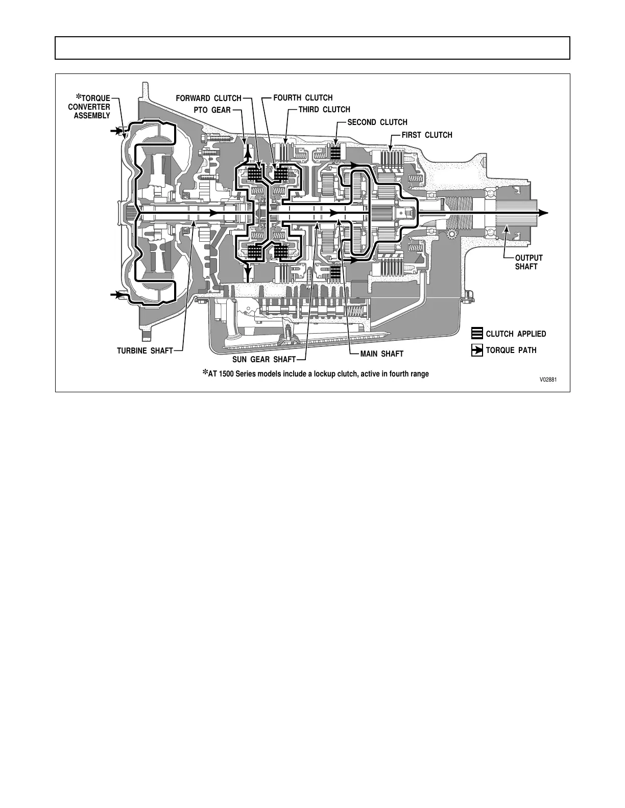
h. Fourth-Range Operation
(Figure 2–5)
. The
forward and fourth clutches are applied. With the
clutches applied, the transmission main shaft and the
sun gear shaft are locked together and rotate as a unit
at turbine speed. With the center and rear sun gears ro-
tating at the same speed and their carriers splined to
the planetary connecting drum, all components rotate
at turbine output speed. The transmission output shaft
is splined to the rear carrier and gives an output ratio
of 1.00:1.
i. Fourth-Range Lockup Operation
(AT 1500
Series Models)
. Except for a momentary shift to con-
verter operation during the upshift, the transmission
shifts directly from third range lockup to fourth range
lockup.
Figure 2–5. Fourth Range Power Flow
;;;;;;;;;;;;;;;;
;;;;;;;;;;;;;;;;
;;;;;;;;;;;;;;;;
;;;;;;;;;;;;;;;;
;;;;;;;;;;;;;;;;
;;;;;;;;;
;;;;;;;;;
;;;;;;;;;
;;;;;;;;;
V02881
TURBINE SHAFT
SUN GEAR SHAFT
PTO GEAR
FORWARD CLUTCH
THIRD CLUTCH
SECOND CLUTCH
FIRST CLUTCH
FOURTH CLUTCH
✽
TORQUE
CONVERTER
ASSEMBLY
MAIN SHAFT
TORQUE PATH
✽
AT 1500 Series models include a lockup clutch, active in fourth range
CLUTCH APPLIED
OUTPUT
SHAFT
 Loading...


