Copyright © 1996 General Motors Corp. 2–11
DESCRIPTION AND OPERATION
(3) Downward movement of the first or
second clutch trimmer displaces transmission fluid
into the trimmer regulator circuit. The trim boost
accumulator valve absorbs the displaced transmission
fluid, allowing for smooth clutch application.
2–19. TORQUE PATHS THROUGH
TRANSMISSION
a. Converter Operation.
Power is transmitted
hydraulically through the torque converter. The engine
drives the converter pump. The pump throws
transmission fluid against the vanes of the turbine,
imparting torque to the converter turbine shaft. From
the turbine, the fluid flows between the vanes of the
stator, and re-enters the converter pump where the
cycle begins again. The torque path through the torque
converter is identical in all drive situations and in
neutral. When the engine is idling, impact of the fluid
upon the turbine vanes is negligible. When the engine
is accelerated, the impact is increased and the torque
produced in the converter turbine shaft can exceed the
engine torque (by an amount equal to the torque ratio
of the converter).
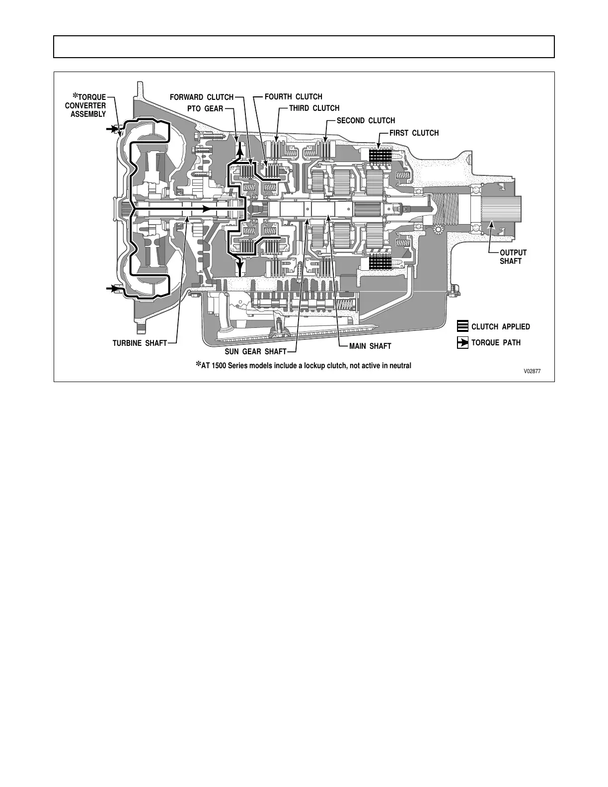
b. Neutral Operation
(Figure 2–1)
(1) Torque produced in the torque converter
is not transmitted beyond the turbine shaft and
forward clutch housing assembly. Only first clutch is
applied. Because two clutches must be applied to
produce output shaft rotation, no output rotation
occurs.
(2) For AT 1500 Series models, the lockup
clutch does not apply during neutral operation.
Figure 2–1. Neutral Power Flow
;;;;;;;;;;;;;;;;
;;;;;;;;;;;;;;;;
;;;;;;;;;;;;;;;;
;;;;;;;;;;;;;;;;
;;;;;;;;;;;;;;;;
;;;;;;;;;
;;;;;;;;;
;;;;;;;;;
;;;;;;;;;
V02877
TURBINE SHAFT
SUN GEAR SHAFT
PTO GEAR
FORWARD CLUTCH
THIRD CLUTCH
SECOND CLUTCH
FIRST CLUTCH
FOURTH CLUTCH
✽
TORQUE
CONVERTER
ASSEMBLY
MAIN SHAFT
TORQUE PATH
✽
AT 1500 Series models include a lockup clutch, not active in neutral
CLUTCH APPLIED
OUTPUT
SHAFT
 Loading...


