7–16 Copyright © 1996 General Motors Corp.
AT 500, 1500 SERIES AUTOMATIC TRANSMISSIONS
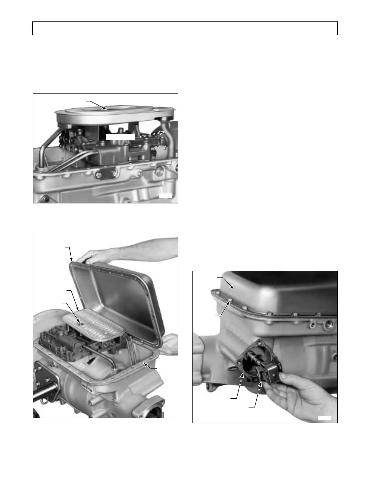
(2) Position the oil pan on the transmission
housing.
(3) Refer to Paragraph 3–10b for oil pan in-
stallation and torque requirements.
Figure 7–34. Installing Oil Filter Screw and Washer
(Models Prior to S/N 3210622842)
Figure 7–35. Installing Transmission Oil Pan
(Shallow Pan Models)
7–11. INSTALLATION OF GOVERNOR,
MODULATOR, AND TORQUE
CONVERTER
a. Governor
(1) Install the governor cover gasket onto the
transmission housing, using oil-soluble grease to re-
tain it (Figure 7–36).
(2) Install the governor assembly by pushing
it inward with a slight rotation (Figure 7–36).
(3) Install the governor cover and retain it
with four
5
⁄16-18 x
9
⁄16 inch bolts (Figure 7–37).
Tighten the bolts to 15–20 lb ft (20–27 N·m).
b. Vacuum Modulator
(1) For earlier models, install the vacuum
modulator valve actuating rod, larger diameter end
first (Figure 7–37). On diesel units (before S/N 22700)
where a mechanical actuator is used, actuator pin 28
(Foldout 12,A) is one diameter. After S/N 22699, rod
28 (with two diameters) is used.
Figure 7–36. Installing Governor Assembly
H02999
INTAKE TUBE
SCREW
H03000
GASKET
OIL FILTER
OIL PAN
SCREW
H02896
OIL PAN
SCREW
(21)
GOVERNOR
ASSEMBLY
GASKET
 Loading...


