Copyright © 1996 General Motors Corp. 3–21
PREVENTIVE MAINTENANCE
PREVENTIVE MAINTENANCE
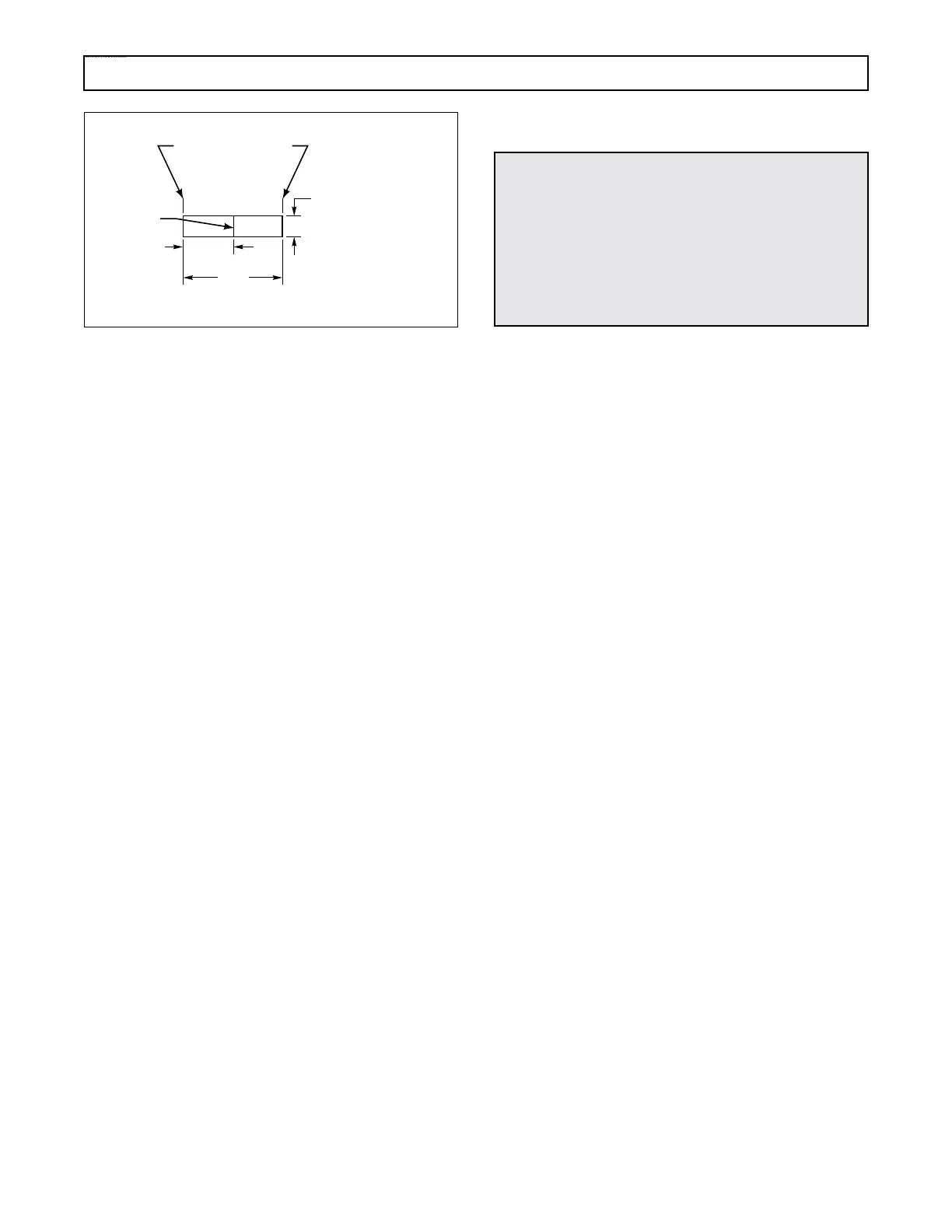
Figure 3–10. Gauge for Comparing Vacuum Modulators
(4) Sleeve alignment check. Roll the main
body of the modulator on a flat surface and observe the
sleeve for concentricity to the can. If the sleeve is con-
centric and the plunger is free, the modulator is ac-
ceptable.
(5) A modulator passing all checks in Steps
(1) through (4) should be an acceptable part.
3–18. TROUBLESHOOTING — BEFORE
REMOVAL AND DURING
OPERATION
a. Determine Cause of Trouble
(1) If the inspections in Paragraph 3–17 do
not reveal the cause of the problem and the vehicle is
operable, further troubleshooting is necessary. Do not
remove the transmission from the vehicle until the
cause of the trouble listed in the troubleshooting chart
is checked.
(2) The engine and transmission must be re-
garded as a single package during troubleshooting. A
thorough study of the description and operation of the
components and hydraulic system will be helpful in
determining the cause.
b. Proper Engine Tuning. In order to make a
thorough test of the transmission while it is mounted
in the vehicle, be sure that the engine is properly tuned
and the fluid level in the transmission is correct. Refer
to Paragraph 3–5 for checking fluid level.
c. Hydraulic Pressure Checking Procedures
(1) Table 3–10 is for checking main pressure
on transmissions having demodulated main pressure.
(2) Table 3–11 is for checking main pressure
on transmissions having modulated main pressure.
(3) Table 3–12 is for checking retarder
pressure.
(4) The pressure check points are shown in
Figures 3–11, 3–12, and 3–13.
3–19. TROUBLESHOOTING —
TRANSMISSION REMOVED
FROM VEHICLE
When the malfunction of a transmission is not ascer-
tained by tests or inspections before removal from
the vehicle, the transmission may be mounted in a
test stand and checked (if a test stand is available).
Particular attention must be given to proper fluid
level and to proper linkage adjustment in every trans-
mission test.
3–20. TROUBLESHOOTING
PROCEDURES
Table 3–13, Troubleshooting Chart, lists possible
causes of transmission troubles and their remedies.
Capital letters indicate the symptom; numerals follow-
ing the symptom indicate several possible causes; cor-
responding numerals in the right column indicate rem-
edies for the causes.
ENDS TO BE SQUARE
WITHIN
1
⁄64 in.
(0.40 mm)
SCRIBED
LINE
V02886
1
⁄2 in.
(12.7 mm)
3
⁄8 in. (131.03 mm) TO
13
⁄32 in. (9.53 mm)
ROUND OR FLAT STOCK
1 in.
(25.4 mm)
WARNING!
Observe safety precautions during hydraulic
pressure check procedures. All personnel must
stand clear of the vehicle. Take precautions
against movement of the vehicle. Be sure that
gauges (vacuum, pressure, tachometer) have ex-
tended lines so that they can be read from inside
the vehicle.
 Loading...


