3–20 Copyright © 1996 General Motors Corp.
AT 500, 1500 SERIES AUTOMATIC TRANSMISSIONS
(3) Modulator comparison check. Using a
comparison gauge (Figure 3–10), compare the load of a
known good modulator with the assembly in question.
• Install a modulator that is known to be
acceptable on either end of the gauge.
• Install the modulator in question on the
opposite end of the gauge.
• Holding the modulators in a horizontal posi-
tion, bring them together under pressure until
either modulator sleeve end just touches the
line in the center of the gauge. The gap be-
tween the opposite modulator sleeve end and
the gauge line must be 0.062 inch (1.57 mm)
or less. If the distance is greater than this
amount, replace the modulator in question.
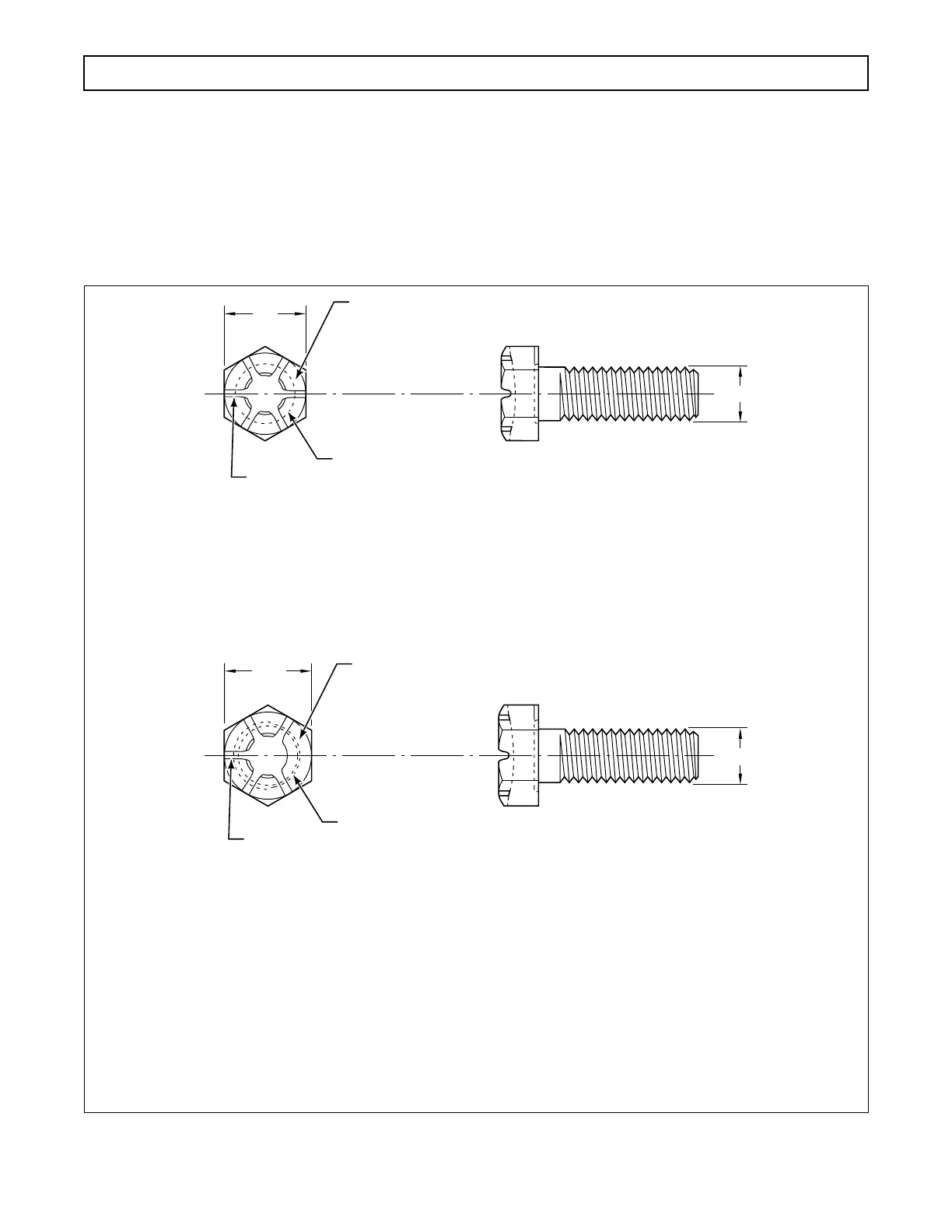
Figure 3–9. Identification of Flange Retaining Bolt
Source and material grade
identification markings to
appear on top of head in
this area
CONSTANT ANNULAR GROOVE
Six (6) radial slots spaced
sixty (60) degrees apart
3
⁄4 in.
1
⁄2 in.
V01301
13
⁄16 in.
1
⁄2 in.
Source and material grade
identification markings to
appear on top of head in
this area
VARYING ANNULAR GROOVE
Five (5) radial slots spaced
sixty (60) degrees apart
EARLIER BOLT
P/N 23014159
STANDARD (TYPE AA PATCH) SAE GRADE 8
3
⁄4 in. HEXAGON HEAD
SIX (6) GRADE ID MARKINGS*
CONSTANT UNDERHEAD FILLET**
LATER BOLT
P/N 29510838
NON-STANDARD (TYPE BH PATCH) SAE GRADE 8
OFFSET,
13
⁄16
in. HEXAGON HEAD
FIVE (5) GRADE ID MARKINGS***
VARYING UNDERHEAD FILLET**
* Radial slots spaced approximately sixty (60) degrees apart.
** Annular groove at the junction of the head bearing surface and the bolt shank.
*** Radial slots spaced approximately sixty (60) degrees apart; may be random relative to hexagon but
shall be oriented such that three (3) wide slots are symmetrically over span of large recess diameter.
 Loading...


