Copyright © 1996 General Motors Corp. 5–5
DISASSEMBLY OF TRANSMISSION
i. Removal of Pump
(1) Rotate the transmission so that the torque
converter end is upward.
(2) Remove the nine bolts and washers from
the outer bolt circle that retain the front support. Dis-
card the washers.
(3) For retarder models, remove six M6-1
bolts 39 (Foldout 7,B) and rubber-coated washers 40.
NOTE:
The pump body can be removed by either of two
methods. If the slide hammer (J 6125-1B) method is
to be used, proceed to Step (4). If puller J 24773-A
(J 39738 AT 1500 Series) method is to be used, skip
Steps (4) and (5) and proceed to Step (6).
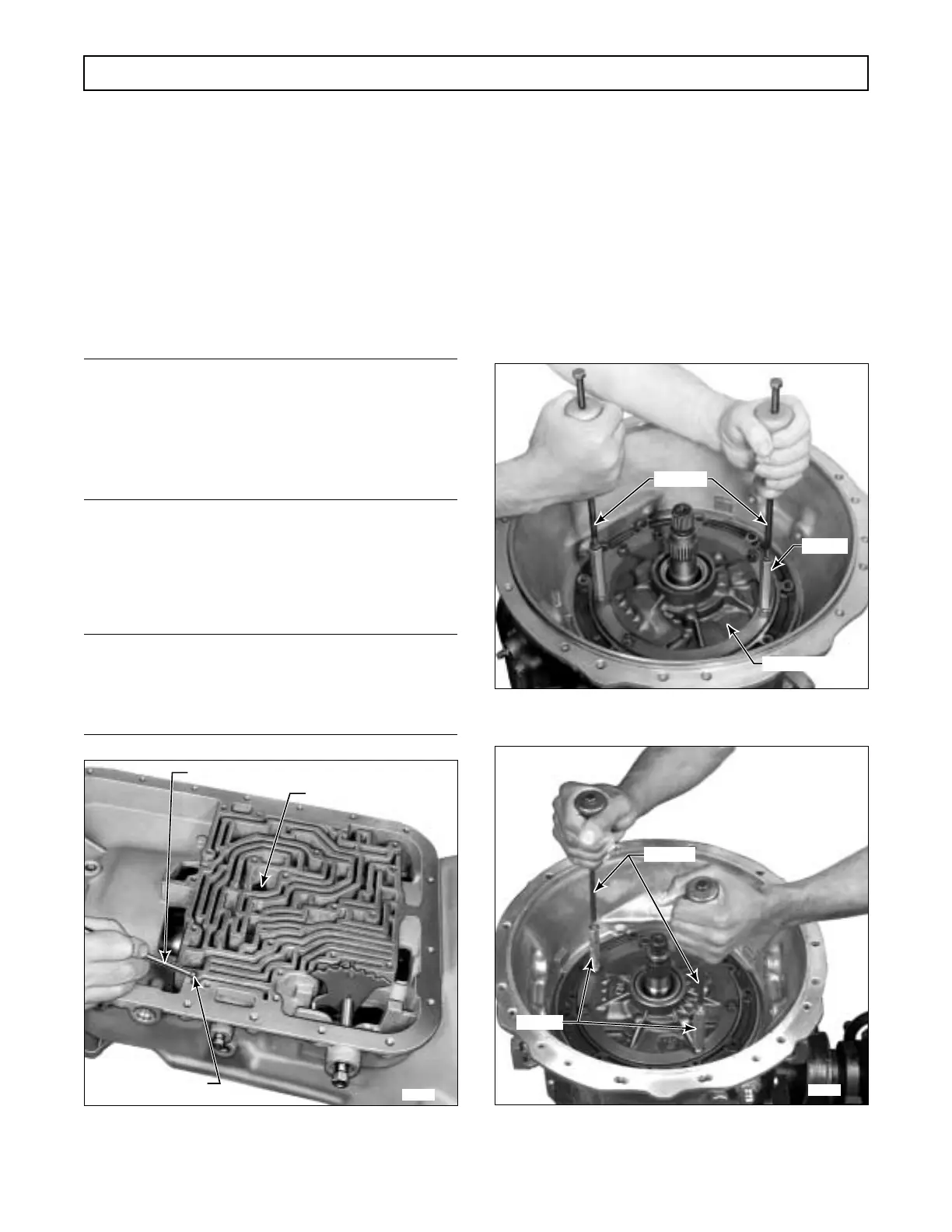
(4) Remove two bolts and washers from the
locations in the pump body as shown in Figure 5–9 or
5–10. Install two J 6125-B slide hammers into
J 6125-2 adapters.
NOTE:
The two holes where the slide hammers are shown
in place in Figures 5–9 and 5–10 are threaded for
the J 6125-2 adapters.
Figure 5–8. Removing Governor Check Ball
(Earlier Models)
(5) Install the assembled slide hammers into
the pump. Hammer upward with the slide hammers to
loosen the pump assembly. When free, lift the pump as-
sembly out of the transmission case. Remove the slide
hammers, and replace the two bolts and washers re-
moved. Do not tighten the bolts. Proceed to Step (7).
(6) Install tool J 24773-A, AT 500 Series; or
J 39738, AT 1500 Series below the ground sleeve
splines. Turn the screw against the turbine shaft, draw-
ing the pump assembly up and out of the main case.
Remove the tool.
Figure 5–9. Removing Pump Assembly
(Models without Retarder)
Figure 5–10. Removing Pump Assembly
(Models with Retarder)
H02899
ANCHOR BOLT
STEEL CHECK BALL
NONMAGNETIC ROD
H02900
J 6125-2
PUMP BODY
J 6125-1B
 Loading...


