5–4 Copyright © 1996 General Motors Corp.
AT 500, 1500 SERIES AUTOMATIC TRANSMISSIONS
(2) On later models, remove the two 3 inch
bolts (Figure 5–7) that retain the first (reverse) clutch
feed tube. Remove the tube.
(3) Remove the sixteen (seventeen or eigh-
teen, earlier models)
1
⁄
4
-20 bolts that retain the main
control valve body and filter spacer (if present).
(4) Install valve body handling tool J 29863
into the drilled boss in center of body and remove the
main control valve body (Figure 5–7) by lifting up-
ward on the body and the attached feed tubes.
(5) Remove the two feed tubes (three, earlier
models). Remove the governor circuit screen, located
in the governor feed tube bore (Figure 5–7).
(6) Refer to Paragraph 6–6 for rebuild of the
main control valve body assembly.
(7) For earlier models, apply a small amount
of oil-soluble grease to the end of a
nonmagnetic
rod
(
1
⁄
4
inch diameter). Insert the rod (greased end first)
into the valve body cavity and remove the steel check
ball (Figure 5–8).
(8) Remove the center support anchor bolt
and flat washer (Figure 5–8).
CAUTION:
Do not allow selector valve 53 (Foldout 11) to
drop out of the main control valve body when the
body is removed. Either tape or wire it in place,
or remove it from the front of the valve body.
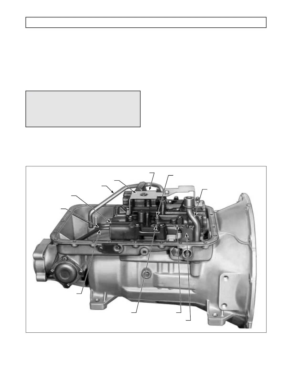
Figure 5–7. Removing Main Control Valve Body
BOLT – LATER MODELS (16)
BOLT – EARLIER MODELS (17) OR (18)
FIRST CLUTCH FEED
TUBE BOLTS, 3 in. (2)
INTAKE TUBE
FILTER SPACER
FILTER SCREEN IN
GOVERNOR FEED
TUBE BORE
GOVERNOR
FEED TUBE
GOVERNOR
PRESSURE TUBE
DETENT SPRING
BOLT, 1
3
⁄4 in.
DETENT SPRING
SELECTOR LEVER
FIRST CLUTCH TUBE
(EARLIER MODELS)
H02898
 Loading...


