6–14 Copyright © 1996 General Motors Corp.
AT 500, 1500 SERIES AUTOMATIC TRANSMISSIONS
(6) If present, remove pipe plug 15 (at the
temperature sending unit location) or, if present, re-
move the temperature sending unit.
b. Assembly
(1) If removed, install
1
⁄2-14 pipe plug 15.
Tighten the plug to 16–20 lb ft (22–27 N
.
m).
(2) Place solenoids 7 in place in transfer
plate 14 and install pins 13. Install
1
⁄16 inch pipe plugs
12 to retain pins 13. Tighten plugs 12 to 35–50 lb in.
(4–5 N
.
m).
(3) In preparation for installation of harness
11, carefully strip wire insulation approximately
1
⁄4
inch (6 mm) (unless insulation crimp is over tight).
Automatic wire stripper J 35615 will remove the insu-
lation and crimp from the old terminal without damag-
ing the wire.
(4) Install harness 11, fitting feedthrough
seal 10 into transfer housing 14.
NOTE:
Terminals with white wires install in one connector
and terminals with red wires install in the other
connector.
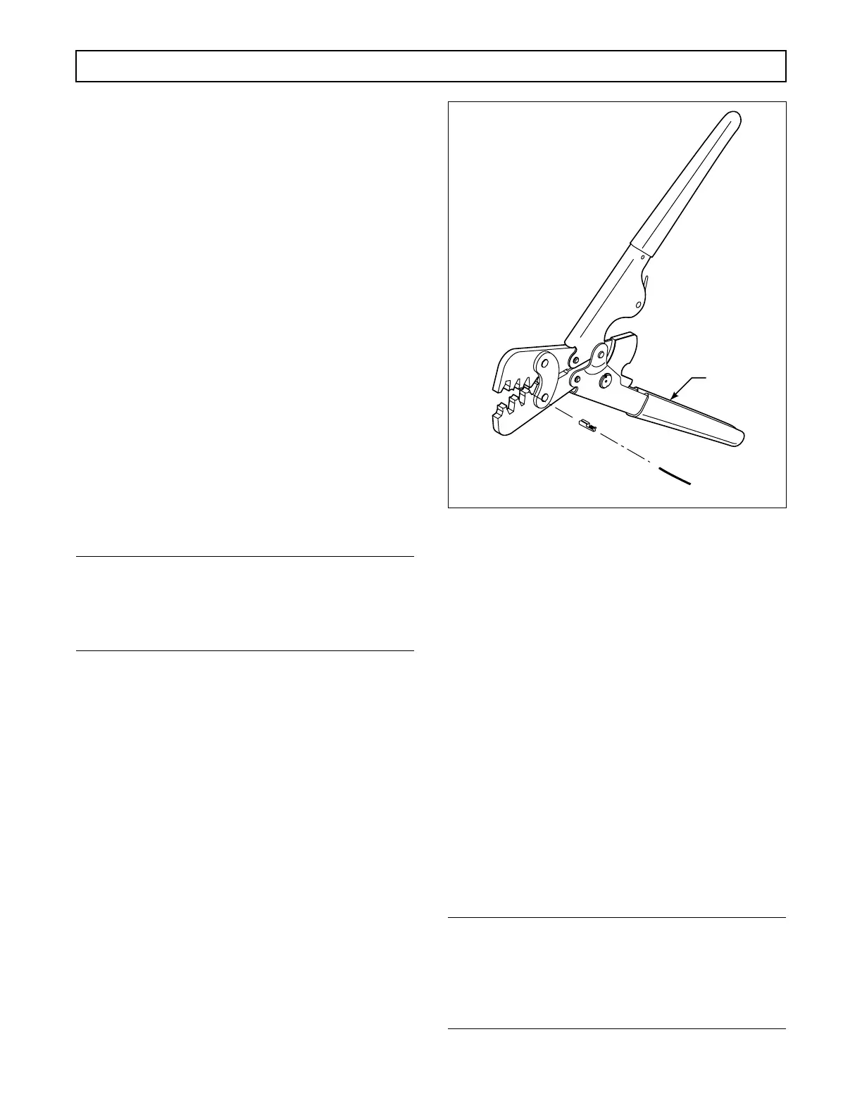
(5) Install the terminals onto connectors 8 as
follows:
• Place core crimp portion of terminal on bed
of Anvil C on crimping tools J 38125-7 and
squeeze the crimper enough to hold the
terminal from dropping (Figure 6–23).
• Position the wire core in the terminal and
squeeze the crimper tool to complete the
core crimp.
• Position the insulation crimp of the terminal
on Anvil D so that the entire insulation
crimp area and a portion of the terminal
between the core and insulation crimp areas
are supported by the anvil. Complete the
insulation crimp.
• Slip the wire through the slot in the
connector and pull to fully seat the
terminal(s).
Figure 6–23. Terminal Installation
(6) Install snapring 9 to retain the harness.
(7) Connect two connectors 8 until they snap
into place on two solenoids 7. The connector with
white wires connects to the H (upper) solenoid; the
connector with the red wires connects to the F (lower)
solenoid.
6–9. OIL PUMP AND FRONT
SUPPORT ASSEMBLY
a. Disassembly (Foldout 7,B)
(1) Remove sealring 13 from front support 16.
(2) Remove six bolts 11 (eight, some mod-
els) and washers 12 from the front of pump body 8.
Discard the washers.
NOTE:
When removing bolts 28 and 29, if the five bolts are
of two different lengths, take note of the size and lo-
cation of the five bolts. The same size bolts will need
to be installed as are removed.
 Loading...


