Copyright © 1996 General Motors Corp. 6–35
REBUILD OF SUBASSEMBLIES
b. Removal of Pinion Components
(1) Using a drill that is slightly smaller than
the pinion pin diameter, drill into the swaged end on
the pins (only one end required). Do not drill into the
carrier. The rear ends of all pinion pins except those in
the center carrier assembly will be drilled. Drill the
front ends of the center assembly pins.
(2) Place press fixture J 25587-1 in a hy-
draulic press. Select the proper spacer and adapter, if
required, from the tool chart and Figure 6–59. Position
these parts (if used) to support the carrier assembly
(drilled ends of pinion pins upward) solidly on the
press fixture.
(3) Install pin remover J 25587-16 into the
ram of the press fixture. Press the pinion pins from the
carrier assembly.
(4) Remove the pinion groups, consisting of
pinions, bearings, and thrust washers.
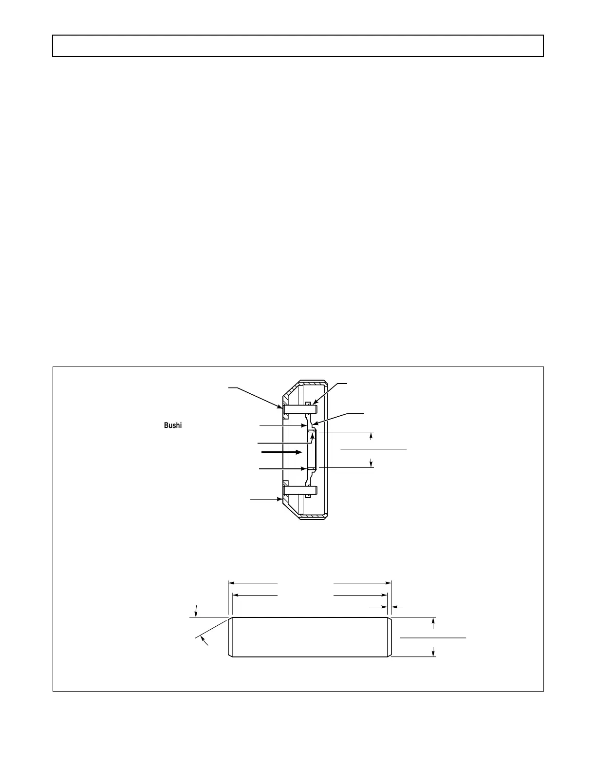
c. Replacing Bushing in
Front Planetary Carrier
(1) Fabricate four dummy pins to the dimen-
sions shown in Figure 6–60.
(2) Place the front carrier on a work table,
rear downward.
(3) Press the bushing from the carrier. Do
not scratch or score the bushing bore. (Refer to Para-
graph 4–5f(1).)
(4) Place the carrier in a press, rear down-
ward.
(5) Apply Loctite
®
Sleeve Retainer No. 601
(or equivalent) to the OD of the new bushing. Install
the bushing using tool J 28501. Press the bushing
flush to 0.010 inch (0.25 mm) below its adjacent sur-
face (Figure 6–60). Remove excess Loctite
®
from the
carrier.
Figure 6–60. Front Carrier Assembly Bushing Installation
Bushing to be flush to 0.010 in.
(0.25 mm) below this surface
Bushing installation load must be
525 LB (2335 N) in direction shown
BUSHING
DUMMY PINS (6)
SURFACE
A
SURFACE B
DIA A
Diameter A must be perpendicular with surface B within 0.001 in. (0.02 mm) TIR.
With respect to surface B and the true position of the six (6) dummy pins,
diameter
A shall be within the total runout specified by C.
Adjust chuck jaws to achieve
“0” TIR (this locates true
position of dummy pins)
C 0.002 in. (0.05 mm) TIR
2.50 in. (63.5 mm)
2.45 in. (62.2 mm)
0.025 in. (0.63 mm)
0.5117 in. (12.997 mm)
0.5114 in. (12.510 mm)
1.7534 in. (44.536 mm)
1.7524 in. (44.510 mm)
DUMMY PIN
30°
V02273.01
 Loading...


