6–36 Copyright © 1996 General Motors Corp.
AT 500, 1500 SERIES AUTOMATIC TRANSMISSIONS
(6) Using a lathe with a four jaw chuck,
mount the carrier with Surface A facing the chuck. In-
sert the four fabricated dummy pins (Figure 6–60) into
the pinion pin holes. Adjust the chuck, centering the
carrier based on Surface B and the runout of the
dummy pins.
(7) Total runout of bushing after boring must
not exceed 0.010 inch (0.25 mm). Use Figure 6–60 as
a guide.
d. Installation of Pinion Components
NOTE:
Lubricate needle rollers and thrust washers before
assembling the pinion groups.
(1) Assemble all the pinion groups for the
carrier assembly. Each group is assembled by inserting
the proper loading pin into the bore of the pinion, in-
stalling the needle roller bearings around the loading
pin, installing a steel thrust washer at each end of the
pinion, and installing a bronze thrust washer onto each
steel thrust washer.
(2) Position the carrier assembly, rear up-
ward (center carrier, front upward). Install all the pin-
ion groups into the planetary carrier, aligning the
loading pins with the pin bores in the carrier.
(3) Install the proper pinion guide pins (Tool
Chart and Figure 6–59), larger diameters first, into the
pinion pin bores. Push the guide pins through the car-
rier until the loading pins drop out.
(4) Position the carrier assembly on the press
fixture, using pin remover and installer adapter
J 25587-2 (if required).
(5) Select the proper pin installer, and install
it into the press fixture ram.
NOTE:
Pin installers are shaped to avoid interference with
bosses on the carrier assemblies. They must be in-
stalled in the ram so that the cutaway portion of the
installer will clear the bosses when the pinion pin is
pressed in.
(6) Place a pinion pin onto the pilot end of
the pin guide located below the press fixture ram.
Press the pinion pin into the carrier until the installer
contacts the carrier.
(7) Install the remaining pinion pins as in-
structed in Step (6).
(8) Remove the carrier assembly from the
press fixture. Install swaging tool holder J 25587-17
into the opening of the press fixture bed. Install a
swaging tool into the holder. Install another swaging
tool into the press fixture ram. Lubricate both ends of
the pinion pins with oil-soluble grease.
(9) Position the carrier assembly, rear up-
ward (center carrier, front upward) on the press fixture.
Use the proper support block to level the carrier while
the lower swaging tool is supporting the lower end of
one pinion pin.
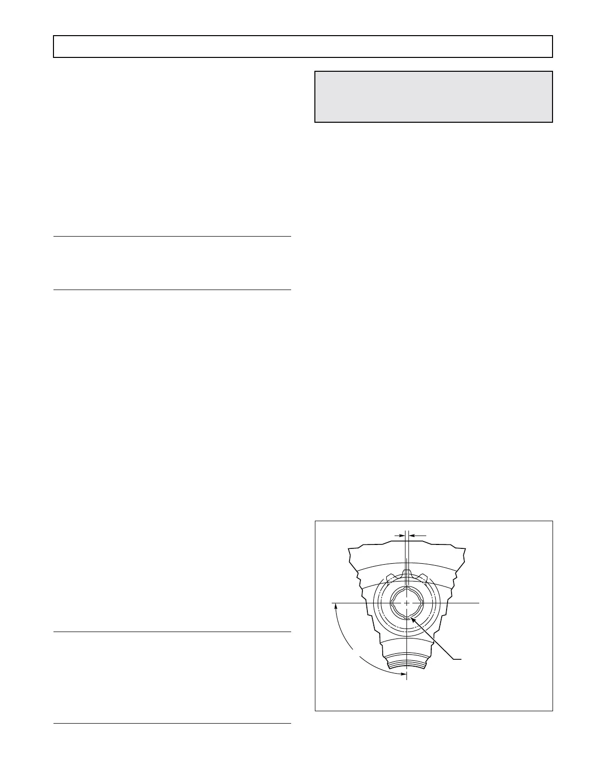
(10) Apply sufficient pressure to the press fix-
ture ram to firmly swage the ends of the pinion pin
against the metal of the carrier. Figure 6–61 illustrates
a typical swage pattern.
Figure 6–61. Typical Swaging Pattern on Pinion Pin
CAUTION:
Do not put pressure on the carrier. Distortion of
the carrier will damage it.
Swage both ends of six
pins securely, as shown.
Gears must turn freely.
90°
0.120 in. (3.048 mm) TYP
V02967
 Loading...


