6–32 Copyright © 1996 General Motors Corp.
AT 500, 1500 SERIES AUTOMATIC TRANSMISSIONS
(21) Install front planetary sun gear 6, ID
spline chamfer (if present) downward, into the front
planetary carrier assembly. Later models do not have a
chamfer of the ID splines.
NOTE:
Thrust washer 5 and sun gear shaft assembly 1 will
be installed after the gear unit is installed into the
transmission.
6–15. TRANSMISSION MAIN
HOUSING ASSEMBLY
a. Disassembly
(1) Remove seal 61 (Foldout 12,B) from the
transmission housing using seal remover tool J 26401.
(2) To remove the manual shift lever, remove
the retainer pin and locknut (Figure 6–56). Begin to
pull the selector shaft out of the housing enough to re-
move the selector lever. The selector lever may have
burred the end of the selector shaft; remove the
burr with a small file before removing the shaft
from the transmission housing.
(3) Do not remove snapring 9 (Foldout
12,A) unless replacement is necessary.
(4) Do not remove the breather from trans-
mission housing 11 unless replacement is necessary. It
is press fit and should be cleaned while in the housing.
Figure 6–56. Selector Shaft Components
Figure 6–57. Governor Support Pin Location
H02961
SELECTOR
SHAFT
LOCKNUT
RETAINER
PIN
SELECTOR
VALVE PIN
SELECTOR
LEVER
V02962
GOVERNOR SUPPORT PIN
Press to dimension
shown
INSPECT
PIN HERE
5.896 in. (149.76 mm)
5.886 in. (149.50 mm)
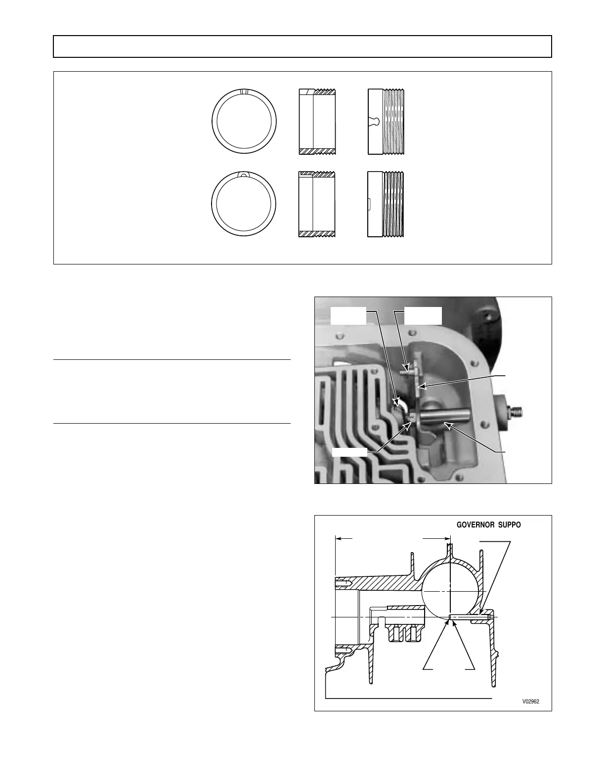
Figure 6–55. Governor Drive Gear Configurations
LARGE “V” SLOT
DEAD END SLOT
EARLIER DESIGN
LATER DESIGN
END VIEW SIDE VIEW TOP VIEW
V02960
 Loading...


