Copyright © 1996 General Motors Corp. 6–31
REBUILD OF SUBASSEMBLIES
(5) If the transmission being rebuilt has a
governor drive gear with a large V slot (Figure 6–55),
install a spring pin 50 (Foldout 10,A) into the output
shaft to a height of 0.150–0.170 inch (3.81–4.31 mm).
If the transmission being rebuilt has a governor drive
gear with a dead-end slot (Figure 6–55), install a
spring pin 50 (Foldout 10,A) to a height of 0.066–
0.076 inch (1.68–1.93 mm).
(6) Install rear planetary sun gear 31 onto
main shaft 4, smaller end first. Secure the sun gear to
the main shaft with spiral retaining ring 34.
(7) Install center ring gear 30, concave side
forward, onto the rear sun gear and secure it with
snapring 29.
(8) Install rear planetary carrier assembly 36
into planetary carrier connecting drum 28 aligning the
broad groove in the drum OD away from the carrier.
Secure the carrier with snapring 43.
NOTE:
• For models after S/N 5070, skip Steps (9) and
(10) and proceed with Step (11).
• For models before S/N 5071, proceed with Step (9).
(9) Install spacer washer 54 and rear plane-
tary ring gear 53 onto the hub of rear planetary car-
rier 36.
(10) Install spacer washer 52 and spiral re-
tainer ring 51 to secure the rear planetary ring gear.
Figure 6–53. Sun Gear Shaft and Bushings
(11) Install ball bearing assembly 44 over the
snapring groove end of output shaft 45. Install output
shaft 45 (snapring groove first) into rear planetary car-
rier assembly 36. Secure it with snapring 35.
(12) Lubricate race 33 and bearing assembly
32 with oil-soluble grease. Install the race and bearing
onto the output shaft adjacent to the rear sun gear.
(13) Install main shaft assembly 4 into rear
planetary carrier 36. Index sun gear 31 with the pin-
ions of the rear planetary carrier.
(14) Install thrust washer 27 against the front
side of the rear sun gear.
(15) Install center planetary carrier assembly
20, smaller diameter end first, into planetary connect-
ing drum 28. Index the carrier splines with the splines
in the connecting drum.
(16) Install center sun gear 19, larger end first
against thrust washer 27.
(17) Install front planetary ring gear 18, larger
diameter end first, into planetary connecting drum 28
and secure it with snapring 17.
(18) Lubricate and install thrust washer 16
onto the hub of front planetary carrier 8.
(19) Install front planetary carrier assembly 8
onto center sun gear 19.
(20) Lubricate and install thrust washer 7 onto
center sun gear 19.
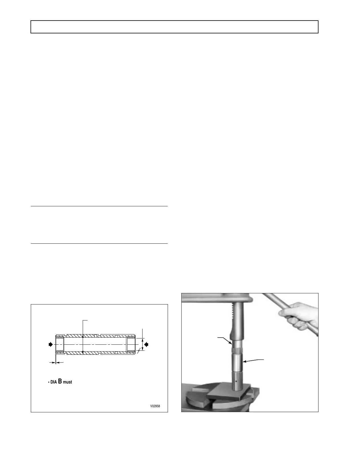
Figure 6–54. Installing Sun Gear Shaft Bushing
V02958
• DIA B must be concentric with DIA A
within 0.002 in. (0.05 mm) TIR
• Each bushing must withstand the specified
load in the indicated direction
Press flush to
0.010 in. (0.25 mm)
below both ends
600
LBS
(2669 N)
600
LBS
(2669 N)
DIA A REF
1.0640 in. (27.02 mm)
1.0625 in. (26.99 mm)
DIA B
BOTH ENDS
H02959
J 23614-A
(for models
without lockup)
J 39737
(for models
with lockup)
SUN GEAR
SHAFT
 Loading...


