3–6 Copyright © 1996 General Motors Corp.
AT 500, 1500 SERIES AUTOMATIC TRANSMISSIONS
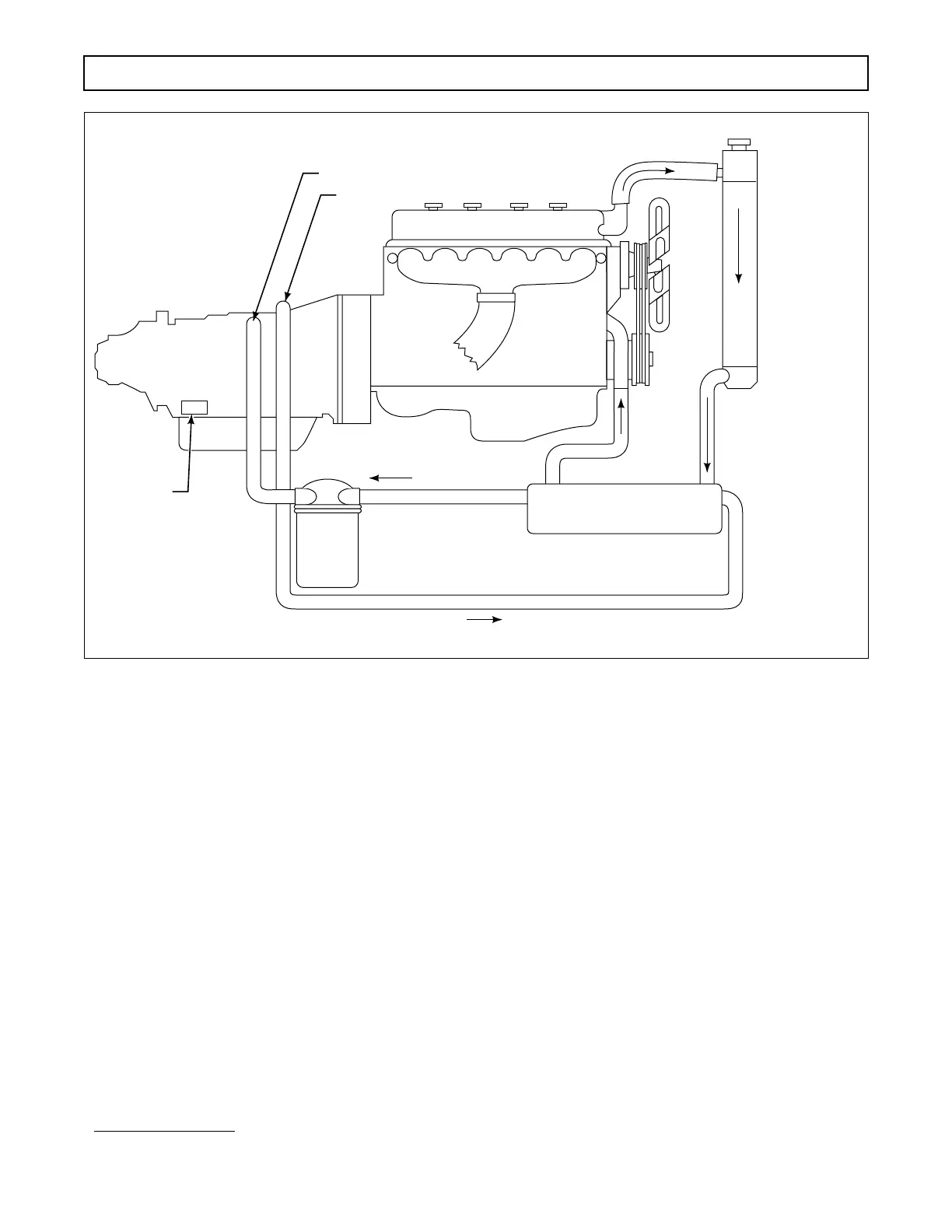
(3) If any doubt exists about the clean-up of
the cooler, replace the cooler.
(4) The auxiliary filter must have a 40 mi-
cron filter element and a maximum filter pressure
drop of 3 psi (21 kPa) at 4.5 gal/min (17 l/min) at
180–200°F (82–93°C). The maximum external circuit
pressure drop must not exceed 35 psi (241 kPa) at 4.5
gal/min (17 l/min) at 180–200°F (82–93°C).
(5) Use one of the following recommended
auxiliary filters:
(6) Install the filter into the line from the
cooler to the transmission. Use a hose long enough to
allow power pack movement. Proper hose size will
permit a minimum flow rate of 4.5 gal/min (17 l/min).
The hose must have a burst pressure of not less than
200 psi (1379 kPa), and a minimum inside diameter at
fittings of 0.391 inch (9.93 mm). The hose must meet
SAE 100 R5 specification, with an operating range of
–40 to +300°F (–40 to 149°C).
(7) The total cooler circuit (to and from the
cooler) pressure drop must not exceed 35 psi (241
kPa) in neutral, at 2400 rpm and at normal operating
temperature. Filter bypass opening pressure on units
not equipped with a pressure indicator (
∆
P switch)
must be 5–9 psi (34–62 kPa). Filter bypass opening
pressure on units equipped with a 5.5–8.5 psi (38–59
kPa) pressure indicator (
∆
P switch) must be 10.5–13.5
psi (72–93 kPa).
(8) External auxiliary filter element change in-
tervals can be determined according to Paragraph 3–8.
Filter Assembly Filter Element
Allison 29501482* Allison 29510922*
AC PM 13-16 PF 897
AC PM 16-1 PF 141
Fram HP 1-1 HP 1
Purolator OF-15C-1 OF-2C-1
Purolator PER-20-10 PER-20
* high efficiency
Figure 3–4. Installation of Auxiliary Filter (Models Without Retarder)
FROM COOLER
TO COOLER
TRANSMISSION
ENGINE
RADIATOR
AUXILIARY
FILTER
TRANSMISSION FLUID TO COOLER
TRANSMISSION FLUID
FROM COOLER
COOLANT
COOLANT
NAMEPLATE
V03129
TYPICAL COOLER
 Loading...


