Installation & Systems Manual RUBIDIUM SERIES
Page 16
1 Introducing the RUBIDIUM SERIES
1.1 Overview
RUBIDIUM SERIES is a modular system which offers flexibility to its users. Various rack mount
frames are available.
On principle, a distinction is made between 1RU (RUB1) and 3RU (RUB3).
One RUB1 module can be plugged to “RUB1 T1” as tabletop unit or for special mounting
and to “RUB1 S1” for 19”/1RU mounting.
Two RUB1 modules can be plugged to “RUB1 D1” or “RUB1 Q1”. Both chassis are
19”/1RU units and include a display. “RUB1 D1” additionally has an integrated power
supply and offers an XLR/DSUB/RJ45 adapter for LTC signals at the rear.
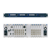
“RUB1 H1” houses up to four RUB1 modules in 19”/1RU space.
“RUB3 H3” chassis provides capacity for 21 slots in 19”/3RU space. It accepts RUB3
modules. Some modules require two slots, other only one slot.
Hot swapping of the rear loading modules is possible. The connectors for inputs and outputs
are a standard part of the module.
Quantity and type of the modules depend on application. In a typical application, the frame
will be equipped with a power supply module (PS) and one or more time code modules (XT,
AT, GT, ...). The RLC connector at the rear of the frame has a 24 V pin (not for “RUB1 D1”)
which enables operation without a power supply module by using external power supply. It is
also possible to supply power from one internal power supply module in one frame to another
frame, via this RLC connector (not for “RUB1 D1”).
The slots within a frame only differ by their individual, hard wired address. Modules which
have an individual configuration (e.g. the time code and video modules, but not the power
supply modules), can be located by their addresses. The PC connector of the frame provides
an interface for the configuration of the modules. Each module can operate as a stand-alone
unit or as an interconnected complete system. The front bus of the frame distributes the
internal “TC_link” interface and the supply voltage.
The “TC_link” interface is connected to the RLC connector at the rear of the frame, too. This
offers a link to modules located in other frames. “FAIL” signals can be used for error detec-
tion: If a total failure occurs in any module in one frame the “FAIL” contacts of this frame’s
relay will close.
Alpermann+V elte
R U B I D I U M SERIES 1
OPER
ERROR
SET
SIGNAL
OPER
ERROR
SET
SIGNAL
OPER
ERROR
SET
SIGNAL
OPER
ERROR
SET
SIGNAL
ADR = 4
ADR = 3
ADR = 2
ADR = 1
PC
RLC
KEY
KEY KEY KEYID
KEY
KEY KEY KEYID
KEY
KEY KEY KEYID
KEY
KEY KEY KEYID
TC_link/FAIL/24V
U
S
B
/
R
S
2
3
2
The “RUB1 H1” frame: Connectors RLC and PC, internal signal distribution