Installation & Systems Manual RUBIDIUM SERIES
Page 61
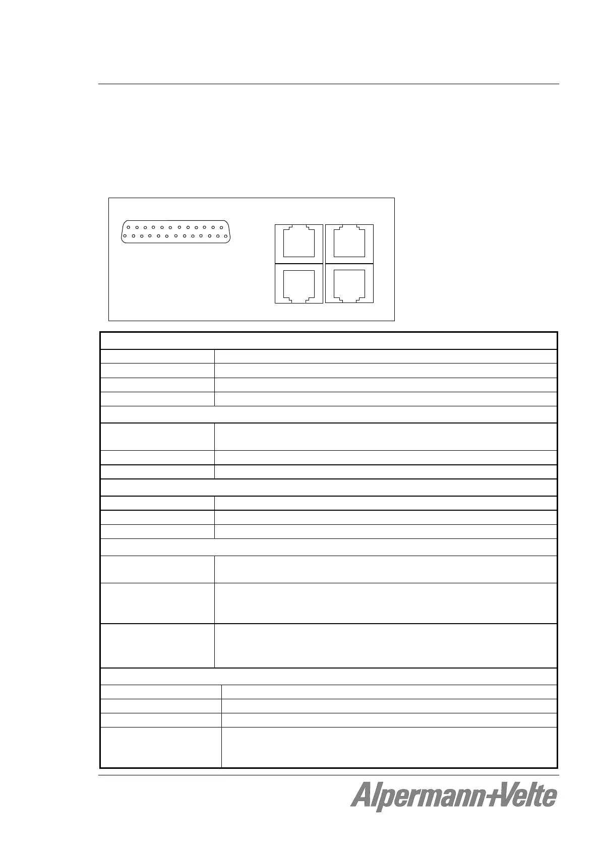
3.26 VI: LTC or IRIG Distribution Amplifier
This module distributes and amplifies one input to six LTC (EBU/SMPTE) or IRIG time code
outputs. A seventh spare output stage together with a change-over relay at each of the six
outputs enables complete redundant output signals. Each output stage is monitored for signal
failures. Alarm outputs are available: GPIs, lamps, LEDs and SNMP traps.
Alpermann+V elte
LOOP
1
OUTPUT
GPI OUT
8 . . . . . 1
8 . . . . . 1
1 . . . . . 8
1 . . . . . 8
INPUT
LTC input:
Format According to ANSI/SMPTE 12M-1-2008, balanced signals
Input impedance
18 k
Signal level 100 mV
p-p
- 5 V
p-p
, auto-ranging
Frequency 19 - 33 frames/s
IRIG input:
Format IRIG-B123 according to IRIG STANDARD 200-98, amplitude modu-
lated carrier signal with 1 kHz carrier frequency, balanced signals
Input impedance
18 k
Signal level 100 mV
p-p
- 5 V
p-p
, auto-ranging
LTC or IRIG output:
Format According to signal input, balanced Signals
Output impedance
< 50
Gain 1 ± 1 %
GPI_1 to GPI_7 outputs, indicating failures:
Output specification Open Collector output of a NPN Darlington transistor.
Max. power dissipation: 200 mW.
“High” state “High” state: external pull-up needed to a positive power source of
less than or equal to 30 VDC, typically 1 k when connected to an
external +5 VDC power source.
“Low“ state “Low“ state: output switched to GND. Maximum collector current =
200 mA DC, not fused.
Collector-emitter saturation voltage: @100mA: typ. 0.9 V ( 1.1 V).
Others:
Operating voltage 12 - 30 VDC
Power consumption 1.6 W maximum (GPI_1 – GPI_7 unconnected)
Weight 0.5 kg approx.
Mechanical 2 circuit boards (W x D): 100 x 160 mm / 3.94 x 6.30 inch
Rear panel: RUB H1: 103 x 44 mm / 4.06 x 1.73 inch
RUB H3: 8HP, 3RU