Installation & Systems Manual RUBIDIUM SERIES
Page 36
3 Modules of the System
3.1 PS: 60 W Power Supply of RUBIDIUM SERIES 1
This module provides power for all the modules in an RUB1 frame. It can be installed at any
slot (location) of the frame just as any other module would. Power is distributed in parallel to
all slots and to the 24V pin at the DSUB female connector RLC at the rear of the frame.
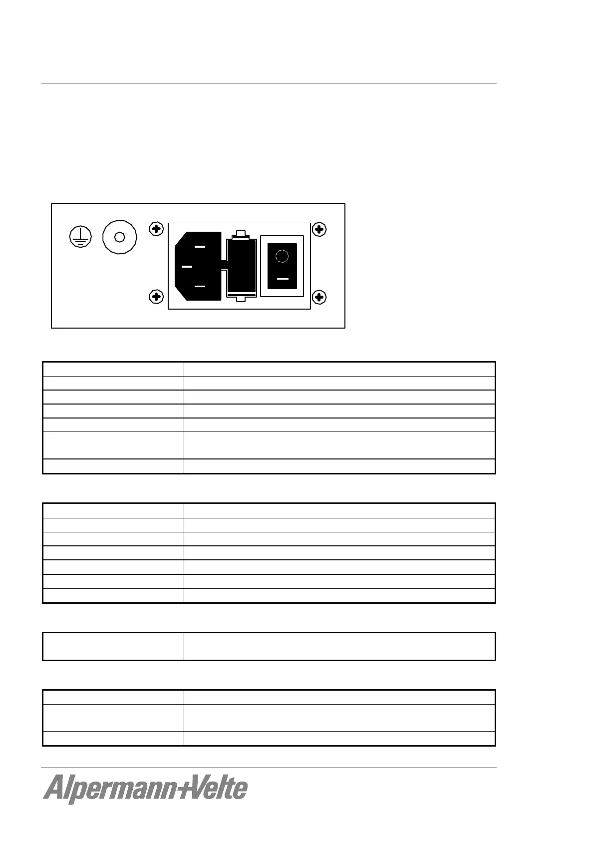
Fuse: 1 A T / 250 V
Fuse
90 - 264 VAC, 47 - 63 Hz, 0.8 A
Alpermann+V elte
Input:
Inlet socket According to IEC/EN 60320-1/C14, protection class 1
Line voltage range 90 - 264 VAC, auto-ranging
Power line frequency 47 - 63 Hz
Input current 800 mA maximum at 90 VAC
Inrush current 50 A maximum @ 264 VAC
Efficiency 86 % typical at 75 % load, 25 °C, nominal line, after 5 mins
warm-up
Line regulation
0.5
%
Output:
Output voltage
23.7 VDC 5
%
Output current 0.05 A minimum, 2.5 A maximum
Turn-on delay 4 secs maximum
Ripple & Noise 1 %
Load regulation
1
%
Temperature coefficient
0.05
% / °C
Hold-up time at 100% load
8 ms typical
Failure relay:
FAIL signal threshold
voltage
If the output voltage (nominal 23.7 V) of the power supply falls
below 20 V approximately.
Others:
Weight 0.5 kg
Mechanical Circuit board (W x D): 100 x 160 mm / 3.94 x 6.30 inch
Rear panel: RUB H1: 103 x 44 mm / 4.06 x 1.73 inch
Power consumption 8.7 W maximum