Installation & Systems Manual RUBIDIUM SERIES
Page 50
3.15 XT: 3G/HD/SD Video Data and Time Code
The hardware consists of a digital video channel (3G/HD/SD), time code in/outputs, serial
interfaces, as well as general purpose interfaces which may be used for various applications.
1
1
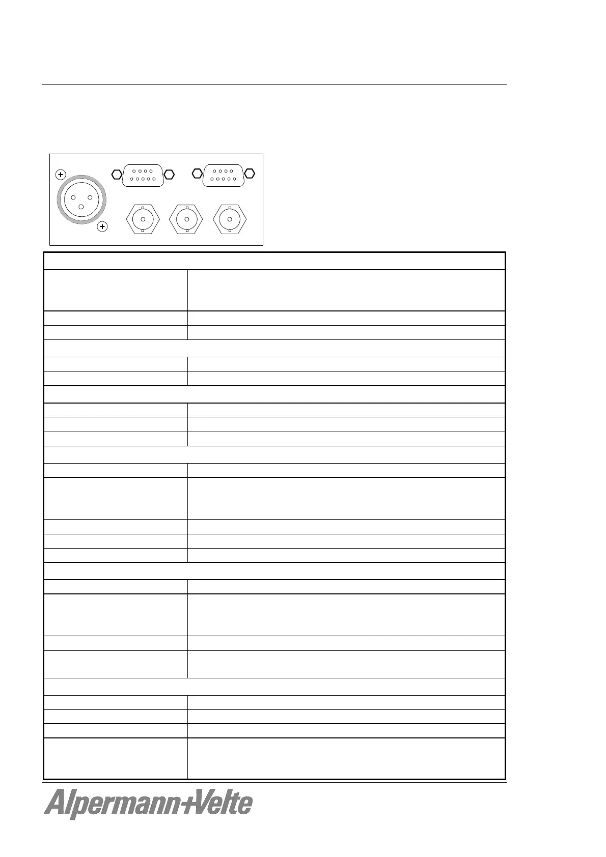
SERIAL / LTC OUT
GPI / LTC IN
VIDEO OUTLOOP OUT
VIDEO IN
LTC
Alpermann+Velte
Video input VIDEO IN:
Format Serial digital video: 3G – SMPTE 424M,
HD – SMPTE 292M,
SD – SMPTE 259M.
Connector
BNC (IEC169-8), 75
Video time codes D-VITC (SMPTE 266M-1994), ATC (SMPTE 12M-2-2008)
Video output LOOP OUT:
Format Same as video input
Connector
BNC (IEC169-8), 75
Video output VIDEO OUT:
Format Same as video input
Connector
BNC (IEC169-8), 75
Video time codes D-VITC (SMPTE 266M-1994), ATC (SMPTE 12M-2-2008)
LTC input:
Format According to ANSI/SMPTE 12M-1-2008
Connector Balanced signals LTC_IN_A and LTC_IN_B:
Via 3-pin XLR female (according to IEC 268-1)
Via 2 pins of the 9-pin DSUB female GPI/LTC IN
Input impedance
18 k
Signal level 100 mV
p-p
- 5 V
p-p
, auto-ranging
Frequency 1.6 - 2500 frames/s
LTC output:
Format According to ANSI/SMPTE 12M-1-2008
Connector Balanced signals LTC_OUT_A and LTC_OUT_B:
Optional via 3-pin XLR male (instead of LTC input)
Via 2 pins of 9-pin DSUB female SERIAL/LTC OUT
Output impedance
< 50
Signal level, adjustable balanced use: from –17 dBu/0,31 V
p-p
to +13 dBu/9,8 V
p-p
unbalanced use: from –23 dBu/0,16 V
p-p
to +7 dBu/4,9 V
p-p
Others:
Operating voltage 12 - 30 VDC
Power consumption 4.7 W maximum
Weight 0.4 kg approx.
Mechanical 2 circuit boards (W x D): 100 x 160 mm / 3.94 x 6.30 inch
Rear panel: RUB H1: 103 x 44 mm / 4.06 x 1.73 inch
RUB H3: 8HP, 3RU