Installation & Systems Manual RUBIDIUM SERIES
Page 72
3.37 SW: Word Clock Monitoring and Changeover Unit
This module can supervise and analyse incoming Word Clock signals of two sources. Each
source can deliver up to four different Word Clock signals. In the event of a failure of one
source, “SW” automatically switches to the other faultless source. The “SW” module is a must
for all Word Clock systems set-ups where a failure proof and redundant Word Clock is a
requirement. Additionally it offers a status monitor indicating errors, failures, and status of all
incoming signals.
DARS IN 2
Alpermann+V elte
DARS OUT
8 . . . . . 1
8 . . . . . 1
1 . . . . . 8 1 . . . . . 8
REF/GPO
CLOCK IN 2
8 . . . . . 1
1 . . . . . 8
CLOCK IN 1
DARS IN 1
CLOCK OUT
12
34
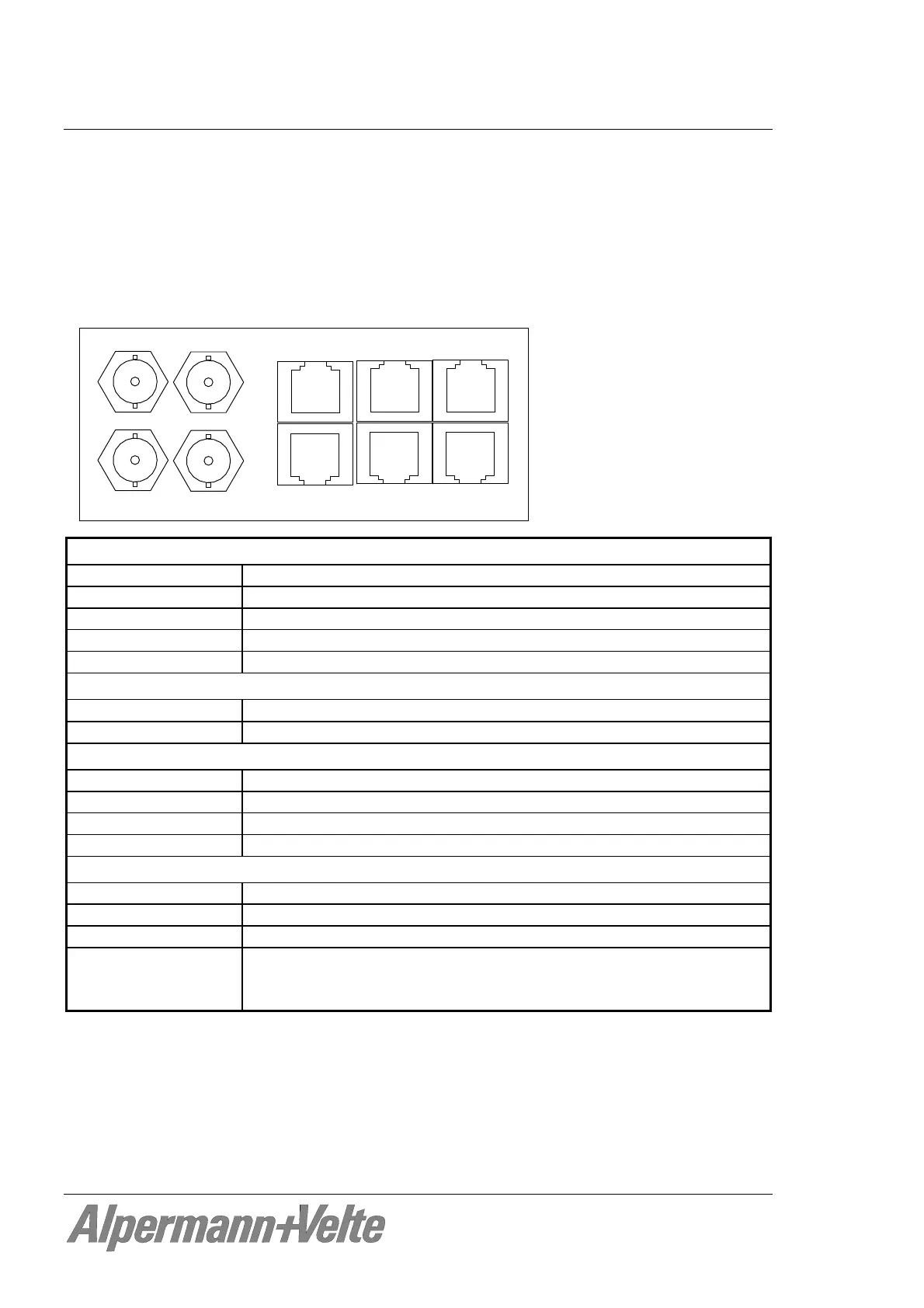
CLOCK IN (2 x RJ45):
Connector RJ45 – suited for direct connection to CLOCK OUT of RUB GW
Signal 4 word clock signals each RJ45
Input impedance ≈ 22 k @ 48 kHz
Signal level 0.5 Vpp to 6.0 Vpp
Frequency 32 kHz to 256 x 48 kHz
4 x CLOCK OUT:
Connector
BNC (IEC169-8), 75
Signal Looped-through via relay from CLOCK IN 1 or 2
REF/GPO:
Connector RJ45
PPS IN Pulse per second, input
RXD IN Reference time & date input, serial data string
GPO_1 ... GPO_4 Open Collector outputs of NPN Darlington transistors
Others:
Operating voltage 12 - 30 V DC
Power consumption 2.1 W maximum
Weight 0.4 kg approx.
Mechanical Standard circuit board (W x D): 100 x 160 mm / 3.94 x 6.30 inch
Rear panel: RUB H1: 103 x 44 mm / 4.06 x 1.73 inch
RUB H3: 8HP, 3RU