Installation & Systems Manual RUBIDIUM SERIES
Page 27
2.1.4 The “RUB1 Q1” Frame
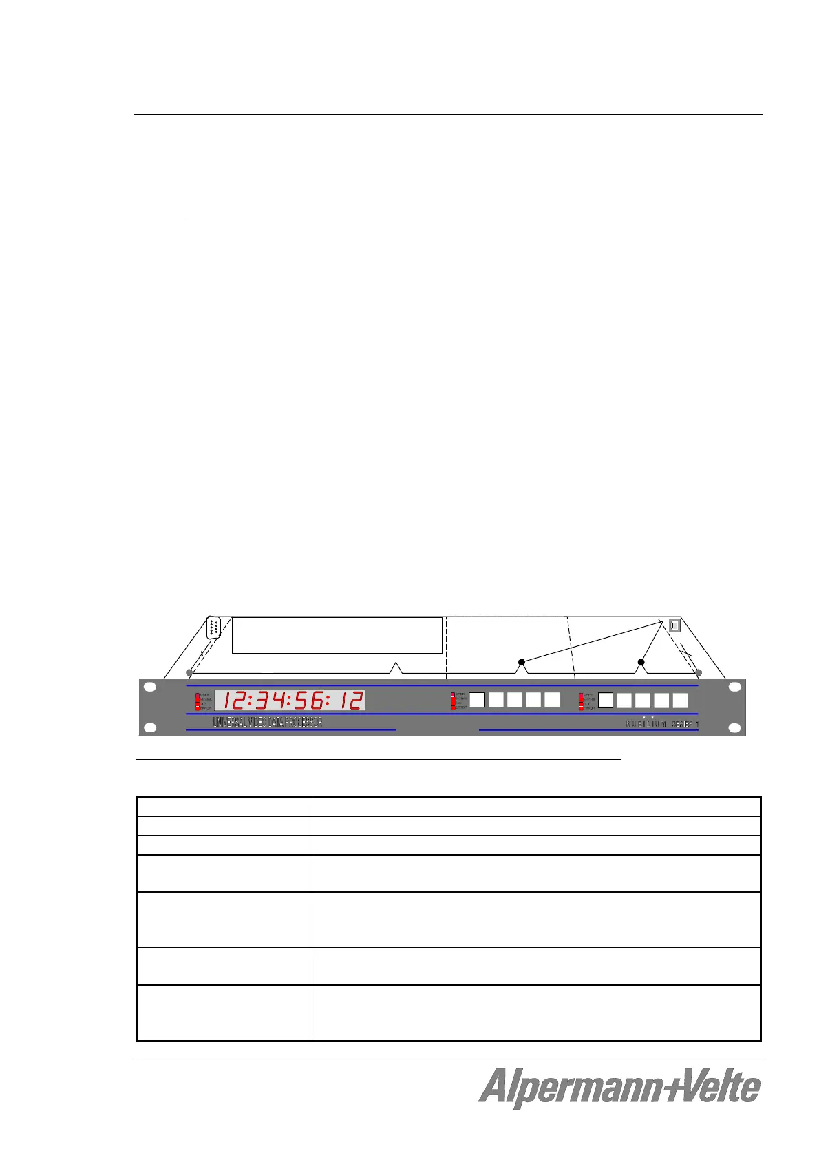
The RUB1 Q1 is a rack mount frame in 19”/1RU space with an 8-digit display.
Chassis
The RUB1 Q1 mount frame was designed to house up to two additional rear loading RUB1
modules in 1RU space. The connectors for inputs and outputs are a standard part of each
module. There is a uniform front for these modules which offers a see-through window for
four status LED’s and cut-outs for four keys and an identification button for each module.
The two slots are assigned to the hard wired addresses 3 and 4 of the frame. Any
configurable module can send data to the display via internal “TC-link” interface. Display
and modules receive power via internal connection. The DC operating voltage can be
supplied at the RLC connector or by a power supply module plugged into this chassis.
The PC connector enables access to modules at addresses 3 and 4. PC programs for
configuration and status monitor are available.
The RLC connector at the rear of the frame combines the “TC_link” interface (which
enables communication to modules located in further chassis), the “FAIL” signal used for
error detection (a total failure of any module in the frame leads to a contact closure), and
the “24 VDC” operating voltage input or output.
ADR = 4
ADR = 3
PC
RLC
D
C/T
C
_
l
i
n
k
/
F
A
I
L
US
B
-
>
R
S
2
3
2
DC / TC_link / FAIL / RS232
Alpermann+V elte
Pin Signal
1 FAIL_A
2 TC_link (RS485, TR-)
3 TC_link (RS485, TR+)
4 FAIL_B
5, 6, 7 GND
8, 9 24 VDC
The “RUB1 Q1” frame: connectors RLC and PC, internal signal distribution
Material High-grade steel, blank
Weight 1 kg approx.
Mounting Standard 19-inch rack, 1U
Dimensions
(without 19“ front plate)
446.5 (W) x 44.5 (H) x 176.5 (D, without RLC DSUB) mm
17.58 x 1.75 x 6.95 inch
Power consumption Max.: 8.5 W (all LEDs with maximum brightness)
Typ.: 6.0 W
Min.: 3.5 W (all LEDs switched off except the OPER LED)
Maximum power
dissipation
Without fan, by free air convection: 20 W
With fan [3 cfm]: 34 W
Technical data of the fan Nominal voltage: DC 12 V ± 15%
Power: 0.84 W
Maximum air flow [cfm]: 3