Installation & Systems Manual RUBIDIUM SERIES
Page 25
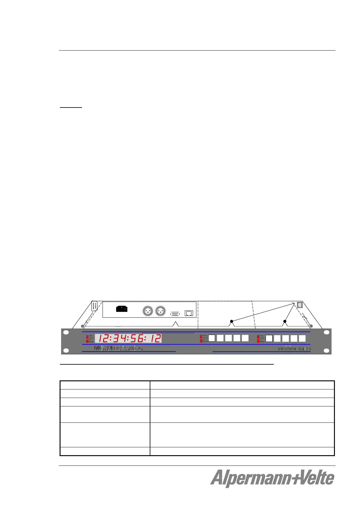
2.1.3 The “RUB1 D1” Frame
The RUB1 D1 is a rack mount frame in 19”/1RU space. It has an integrated power supply, an
8-digit LED display at the front, and an XLR-DSUB-RJ45 adapter for LTC signals at the rear.
Chassis
The RUB1 D1 mount frame was designed to house up to two additional rear loading RUB1
modules in 1RU space. The connectors for inputs and outputs are a standard part of each
module. There is a uniform front for these modules which offers a see-through window for
four status LED’s and cut-outs for four keys and an identification button for each module.
The two slots are assigned to the hard wired addresses 3 and 4 of the frame. Modules
which have an individual configuration (e.g. the time code and video modules, but not the
power supply modules), can be located by their addresses. Each module can operate as a
stand-alone unit or as an interconnected complete system. An internal “TC-link” interface
is used for the intercommunication between modules. The front bus of the frame
distributes this interface and the 24 V output of the integrated power supply.
The PC connector enables access to modules at addresses 3 and 4. PC programs for
configuration and status monitor are available.
The RLC connector at the rear of the frame offers a link to modules located in other
frames (via “TC_link”). The “FAIL” signals at this connector can be used for error detec-
tion: If a total failure occurs in any module in one frame the “FAIL” contacts of this
frame’s relay will close. In contrast to the RUB1 H1 chassis the RLC connector does not
have the 24 V connected, neither as input nor as output.
ADR = 4
ADR = 3
PC
RLC
T
C
_l
i
n
k
/
F
A
IL
Alpermann+Velte
Pin Signal
1 FAIL_A
2 TC_link (RS485, TR-)
3 TC_link (RS485, TR+)
4 FAIL_B
5 GND
U
S
B
-
>
R
S
2
3
2
DC / TC_link / FAIL / RS232
The “RUB1 D1” frame: Connectors RLC and PC, internal signal distribution
Material High-grade steel, blank
Weight 2.4 kg approx.
Mounting Standard 19-inch rack, 1U
Dimensions
(without 19“ front plate)
446.5 (W) x 44.5 (H) x 176.5 (D, without DSUBs) mm
17.58 x 1.75 x 6.95 inch
Power consumption Max.: 7.0 W (all LEDs with maximum brightness)
Typ.: 5.0 W
Min.: 2.0 W (all LEDs switched off except the OPER LED)
Maximum power dissipation Without fan, by free air convection: 20 W