Installation & Systems Manual RUBIDIUM SERIES
Page 3
CONTENTS
A1 REVISION HISTORY
A2 COPYRIGHT
A3 WARRANTY
A4 UNPACKING/SHIPPING/REPACKAGING INFORMATION
A5 SAFETY INSTRUCTIONS
A6 EC DECLARATION OF CONFORMITY
1 INTRODUCING THE RUBIDIUM SERIES 16
1.1 OVERVIEW 16
1.2 CONFIGURATION OF THE MODULES: THE PC CONNECTOR 17
1.3 SYSTEM EXTENSIONS: THE RLC CONNECTOR AND FURTHER INTERFACES
18
1.3.1 The “TC_link” Interface 18
1.3.2 The FAIL Signals: Error Detecting 19
1.3.3 24 VDC 19
1.3.4 Ethernet: The Gate to a Local Area Network 19
1.3.5 Local Serial Interfaces 19
1.4 MODULE AND SYSTEM CONFIGURATION 20
1.4.1 Overview 20
1.4.2 Unique Identification of a Module and a Frame 20
1.4.3 Installation of a Module 21
1.4.4 Update 21
2 THE RUBIDIUM FRAMES 22
2.1 RUBIDIUM SERIES 1 22
2.1.1 The “RUB1 S1” and “RUB1 T1” Chassis 22
2.1.2 The “RUB1 H1” Frame 24
2.1.3 The “RUB1 D1” Frame 25
2.1.4 The “RUB1 Q1” Frame 27
2.1.5 Plug-In a Module 29
2.1.6 Remove a Module 30
2.1.7 The Fan Module: Fan, Frame Address, TC_link Termination 31
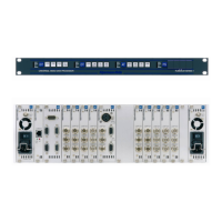
2.2 RUBIDIUM SERIES 3 32
2.2.1 The “RUB3 H3” Frame 32
2.2.2 Plug-In a Module 33
2.2.3 Remove a Module 34
2.2.4 The RC Module: Fan Control, Frame Address, TC_link Termination 35
2.2.5 Exchange a Fan 35