Installation & Systems Manual RUBIDIUM SERIES
Page 68
3.33 SL: LTC Monitoring and Changeover Unit
This module can frame accurate and in real-time compare and contrast two incoming LTCs
for indescribable differences. In the event of a failure, “SL” automatically switches to the other
faultless source. The SL module is a must for all time code systems where failure proof LTC is a
requirement. This includes real-time and MTD Time Timer Timecode applications. Additionally,
it monitors LTC and reference errors, LTC/LTC and LTC/reference differences, and it makes
status information about all sources available.
1
LTC/MTD OUT
LTC/MTD IN 2
Alperm ann+V elte
GPI OUT
REF IN
REF OUT
REF OUT
LTC/MTD IN 1
LTC/MTD OUT
8 . . . . . 1 8 . . . . . 1
8 . . . . . 1
8 . . . . . 1
1 . . . . . 8
1 . . . . . 8
1 . . . . . 8
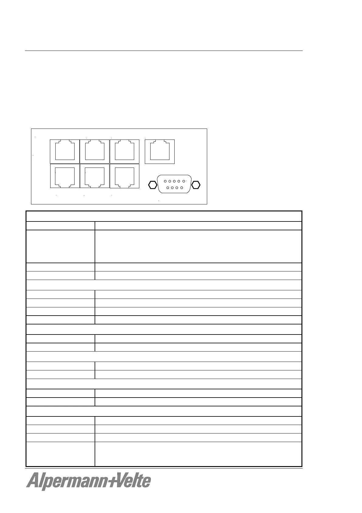
LTC/MTD IN (2 x RJ45):
RS485 Balanced in- or outputs of a RS485 serial interface
LTC IN Format: ANSI/SMPTE 12M-1-2008, balanced
Signal level: 100 mV
p-p
- 5 V
p-p
, auto-ranging
Input impedance: 18 k
Frequency: 19 - 33 frames/s
SERIAL IN Serial time & date data string
TELEGRAM IN Impulse telegram
LTC/MTD OUT (RJ45 and DSUB9F):
RS485 RS485 serial interface, hard-wired with signals at LTC/MTD IN
LTC OUT Balanced LTC output, switched via relay to one input
SERIAL OUT Serial time & date data string, switched via relay to one input
TELEGRAM OUT Impulse telegram, switched via relay to one input
REF IN (RJ45):
PPS IN Pulse per second, input
RXD IN Reference time & date input, serial data string
REF OUT (2 x RJ45):
PPS OUT Pulse per second output, hard-wired with signal at REF IN
TXD OUT Reference time & date output, hard-wired with signal at REF IN
GPI OUT (RJ45):
FAIL Failure signals
WARNING Warning signals
Others:
Operating voltage 12 - 30 V DC
Power consumption 1.5 W maximum
Weight 0.3 kg approx.
Mechanical Standard circuit board (W x D): 100 x 160 mm / 3.94 x 6.30 inch
Rear panel: RUB H1: 103 x 44 mm / 4.06 x 1.73 inch
RUB H3: 8HP, 3RU