Installation & Systems Manual RUBIDIUM SERIES
Page 75
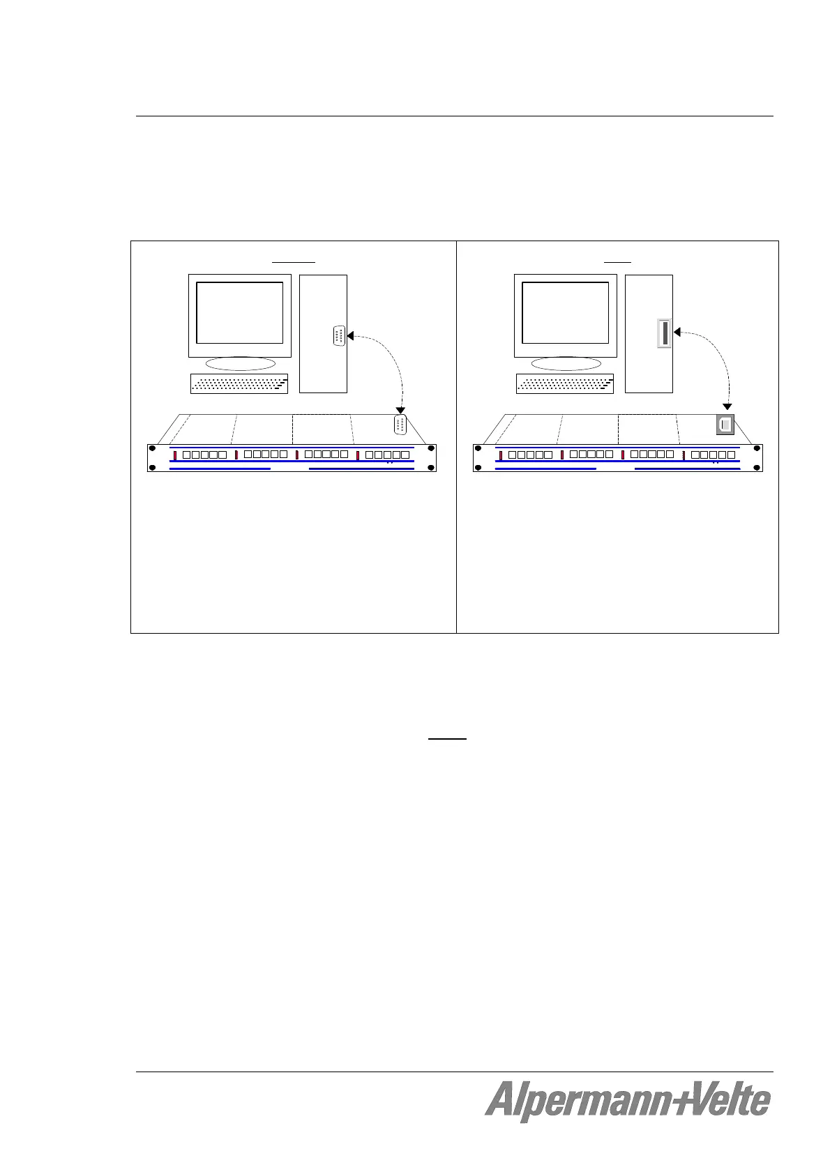
4.1.3 Connection to RUBIDIUM SERIES Chassis
The RUBIDIUM CONFIGURATION program uses either a RS232 serial interface or a USB
interface in order to communicate with a module. The PC connector at the Rubidium chassis
determines the kind of this interface.
RS232
Alpermann+Velte
R U B I D I U M SERIES 1
OPER
ERROR
SET
SIGNAL
OPER
ERROR
SET
SIGNAL
OPER
ERROR
SET
SIGNAL
OPER
ERROR
SET
SIGNAL
UNIT 1
UNIT 2
UNIT 3
UNIT 4
PC
RS232
COM__
The connection must be made with a 1:1
DSUB9 male to female extension cord,
between a PC’s RS 232 serial port (COM...)
and the PC connector on the RUBIDIUM
SERIES chassis. If the Rubidium’s PC connec-
tor is being used for other applications,
temporarily disconnect this cable while using
this set-up program.
USB
Alpermann+Velte
R U B I D I U M SERIES 1
OPER
ERROR
SET
SIGNAL
OPER
ERROR
SET
SIGNAL
OPER
ERROR
SET
SIGNAL
OPER
ERROR
SET
SIGNAL
UNIT 1
UNIT 2
UNIT 3
UNIT 4
PC
USB
Use a common “Type A to Type B” cable to
connect the PC connector on the RUBIDIUM
SERIES chassis to an USB port at your
computer.
Now turn on the power of the Rubidium modules and start the Rubidium Config.exe
program on your PC.
A communication can be established to a single
module only. Please select the module that
you would like to configure by choosing unit 1 (= located most left front view) up to unit 4
(RUB1 chassis) or up to unit 21 (RUB3 chassis).