Installation & Systems Manual RUBIDIUM SERIES
Page 23
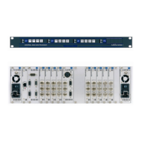
The front offers a see-through window for four status LED’s and cut-outs for 4 keys and an
identification button for the module.
The PC connector at the rear of the chassis enables access to the module. PC programs
for configuration and status monitor are available.
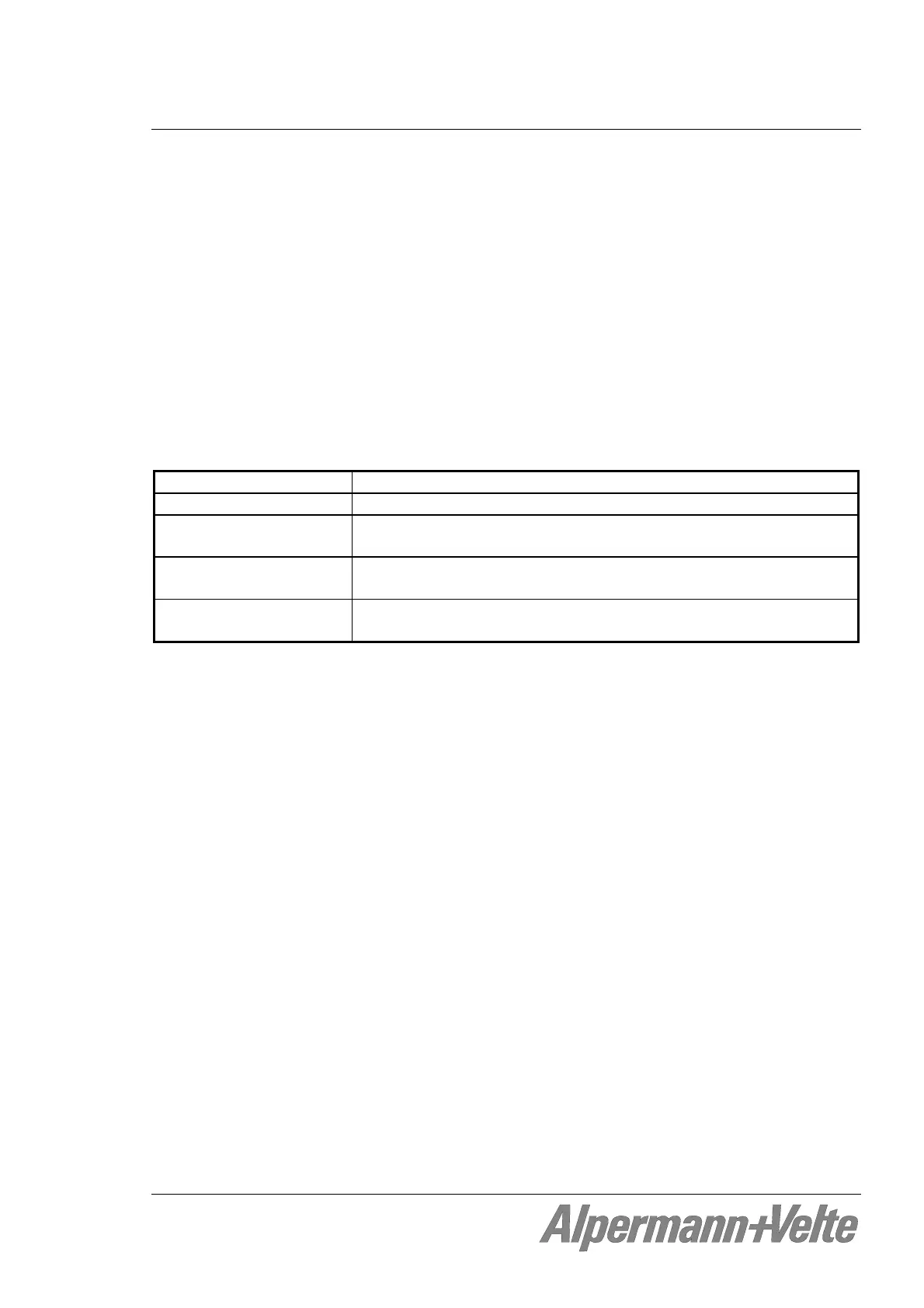
The RLC connector at the rear of the chassis serves to input the operating voltage to the
module. Furthermore it has the “FAIL” and “TC_link” signals. The RUB1 PE power supply
unit can be plugged directly to this connector. The “FAIL” signals can be used for error
detection: If a total failure occurs in the module the “FAIL” contacts of this module’s relay
will close. Via the “TC_link” interface a link to modules located in other frames can be
established.
Material Covers: High-grade steel, blank; cheeks: Aluminium
Weight 0.6 kg approx.
Dimensions 143 (W) x 44.5 (H) x 180 (D, without DSUBs) mm
5.63 x 1.75 x 7.09 inch
Operating voltage and
Operating current
12 – 30 VDC (for standard Rubidium modules),
1 A maximum
Maximum power
dissipation
6.5 W