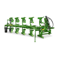
Mounting and dismounting the plough
BAG0172.7 02.20
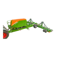
5.1 Mounting the plough
Stand the plough in working position and connect to tractor as
follows:
• For models with four-
share design and above, the mounting axle
diameter must have a pin diameter of 36 mm or ball diameter of
64 mm.
• Use the correct mounting axle:
Mounting axle
Cat. 2/28
= Shoulder size 825
Cat. 2/ 36
= Shoulder size 825
Cat. 3/ 36
= Shoulder size 965
• Set the tractor hydraulic system to position control.
• Connect lower links to the plough's mounting axle and secure
with linch pins
• Release stand support, turn by 90° and secure again.
• Insert the tractor upper link into one of the three elongated slots
or holes in the headstock with connecting pin and secure with
linch pin. Preferably use long slot in connecting body -
specifically for multi-furrow (4-,5-,6-share) ploughs - so that
upper connecting rod can move freely during ploughing
(Advantageous on hilly ground). Connect the top link such that
the connection point on the plough is higher than the connection
point on the tractor during operation.
• Connect the hydraulic hose or hoses to the tractor control unit.
• For plough work set hydraulic control to pulling force or
combined control. Also observe the operating manual of the
tractor manufacturer.
5.2 Dismounting the plough
• Before lowering the plough onto the ground, it is advisable to
ensure that the turnover system is in an upright position by using
the pitch adjustment spindle and turning cylinder. Turning gear
that is not upright can cause a problem when remounting the
plough. Before the next operation, return wheel camber spindle
to its original setting.
• Park the plough on solid and level ground.
• Switch the hydraulic system to position control.
• Turn the plough beam to working position and switch the engine
off.
• Move the control lever for turning of plough back and forth a few
times to build up pressure.
• Remove the upper link from the mounting body.
• Uncouple hydraulic hose or hoses from the tractor and replace
protective caps.
• Release stand supports, fold down and secure again with linch
pin.
• Disconnect lower links from the mounting axle.
 Loading...