4-2 | Model 241CE II Hydrocarbon Dewpoint Analyzer
Introduction to the User Interface
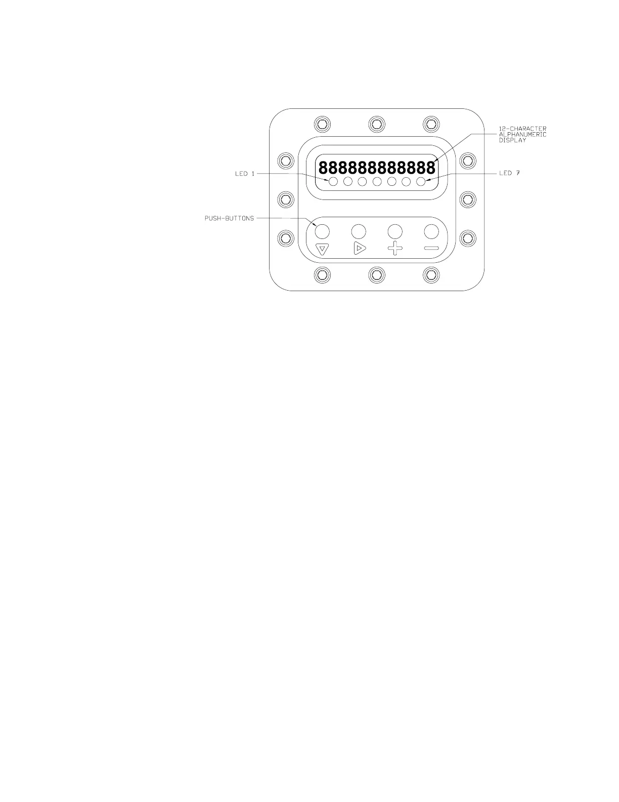
Figure 4-1 illustrates the layout of the analyzer User Interface.
The User Interface is made up of two areas:
• Display Screen/LEDs
Consists of one self-illuminated line capable of displaying up to 12
alphanumeric characters and one row of seven LEDs. The information
displayed depends on the current operation mode.
- The self-illuminated line displays the results of the most recent
measurement cycle, mirror temperature, run time, and Status
Code (SCode).
To change an operating parameter, it must be active on the display.
The display line flashes when the Model 241CE II Analyzer is in
Standby Mode (a Fault alarm is present).
- The LEDs provide a visual indicator of the built-in diagnostics
function. When a LED is On, it indicates the alarm condition as-
sociated with the LED currently exists. For more information about
this diagnostics tool, see “Types of Alarms” in Chapter 6.
Figure 4-1.
User Interface
description.

 Loading...


