14
Installation, Operation and Maintenance Manual
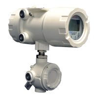
OXYvisor Optical Oxygen Analyzer
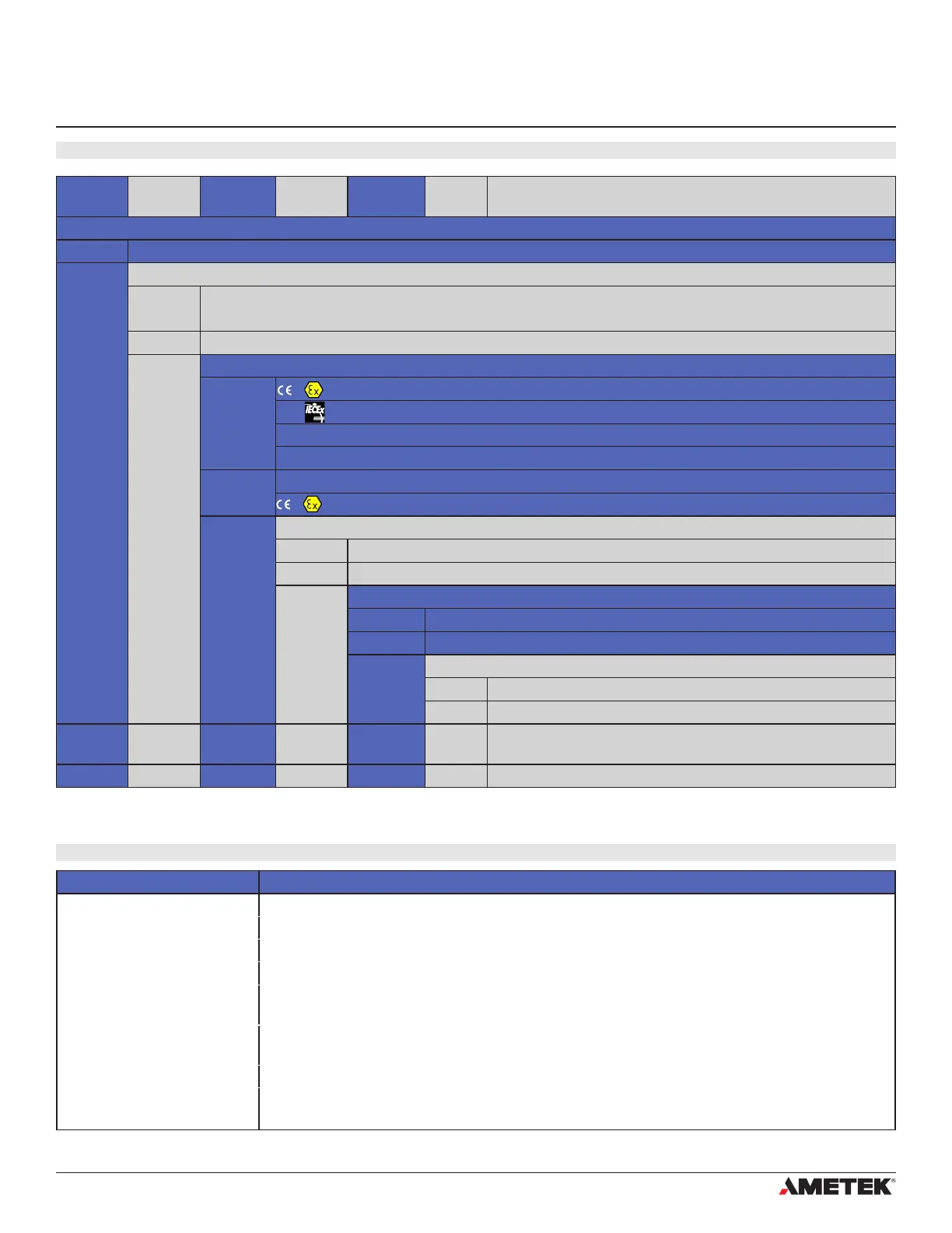
2.3 OXYvisor Conguraon - Product Model Selecon
2�4 OXYvisor Accessories
Section 2
Technical Product Specication
Part Number Description
B5008-112x Wall Mount Kit - 316 SS with Swivel
B5008-1125 Pipe Mount Kit - 316 SS (1-1/2" - 2-1/4" pipe)
B5012- Compact USB memory stick for data logging and rmware upgrades, 8 GB
B4000-1 Compact sunshade, powder coated, highly recommended for outdoor installations
B5500-1 Trace Level - AutoCal Kit: Test Gas Bottles (N6 & 25 ppm), analytical grade regulators, pipe/wall
stand for bottles, (requires AutoCal SCP) [customer supplied 1/4” 316 SS tubing required]
B5500-2 Trace Level - AutoCal Kit: Test Gas Bottles (N6 & 50 ppm), analytical grade regulators, pipe/wall
stand for bottles, (requires AutoCal SCP) [customer supplied 1/4” 316 SS tubing required]
BOS Data Sheet (link) For BOS Sensor Selection see BOS Specication Data Sheet
SCP Data Sheet (link) For Sample Calibration Panel options, AutoCal or Manual, see SCP Specication Data Sheet
Analyzer Power
Agency
Approval
Sensor
Style
Mounting
Orientation
Conduit
Entries
OXYvisor Base Model Number
BOA OXYvisor - Barben Oxygen Analyzer
Input Power
DC 22 to 26.5 VDC, 5W (4-wire, line powered analyzer, this is NOT a loop powered analyzer. Requires two wires
for DC power and two separate wires for 4-20 mA output)
AC 85 to 264 VAC, 47-63 Hz, 6 W (4-wire, line powered analyzer)
Agency Approval
1
II 2 G Ex db op is IIC T4 Gb // ATEX
Ex db op is IIC T4 Gb // IEC / EU
Class I Zone 1 AEx db op is IIC T4 Gb // US (NEC 505)
Ex db op is IIC T4 Gb // CA (CEC Section 18)
2 Class I Division 2 Group A, B, C, D T4a // US (NEC 500) and CA (CEC Annex J18)
II 3 G Ex ec ic op is IIC T4 Gc // PENDING CERTIFICATION FROM NRTL
Sensor Style
SFP Standard Fiber Patch
- Saved for future use - Integral Wands with lengths (2.5, 5.0 and 10 M)
Mounting Orientation
B Junction Box placed below main enclosure, ber optic exits bottom (as shown)
- Saved for future use - other orientations w/ display and JB
Conduit Entries
SI 25 mm Conduit Entries
AM 3/4” FNPT Conduit Entries
Analyzer Power
Agency
Approval
Sensor
Style
Mount
Orientation
Conduit
Entries
BOA DC 2 SFP B AM Typical Analyzer Model Number