73
Installation, Operation & Maintenance Manual
OXYvisor Optical Oxygen Analyzer
A4 - Dri and Sample Rate
Auto O
2
Calibration Setup
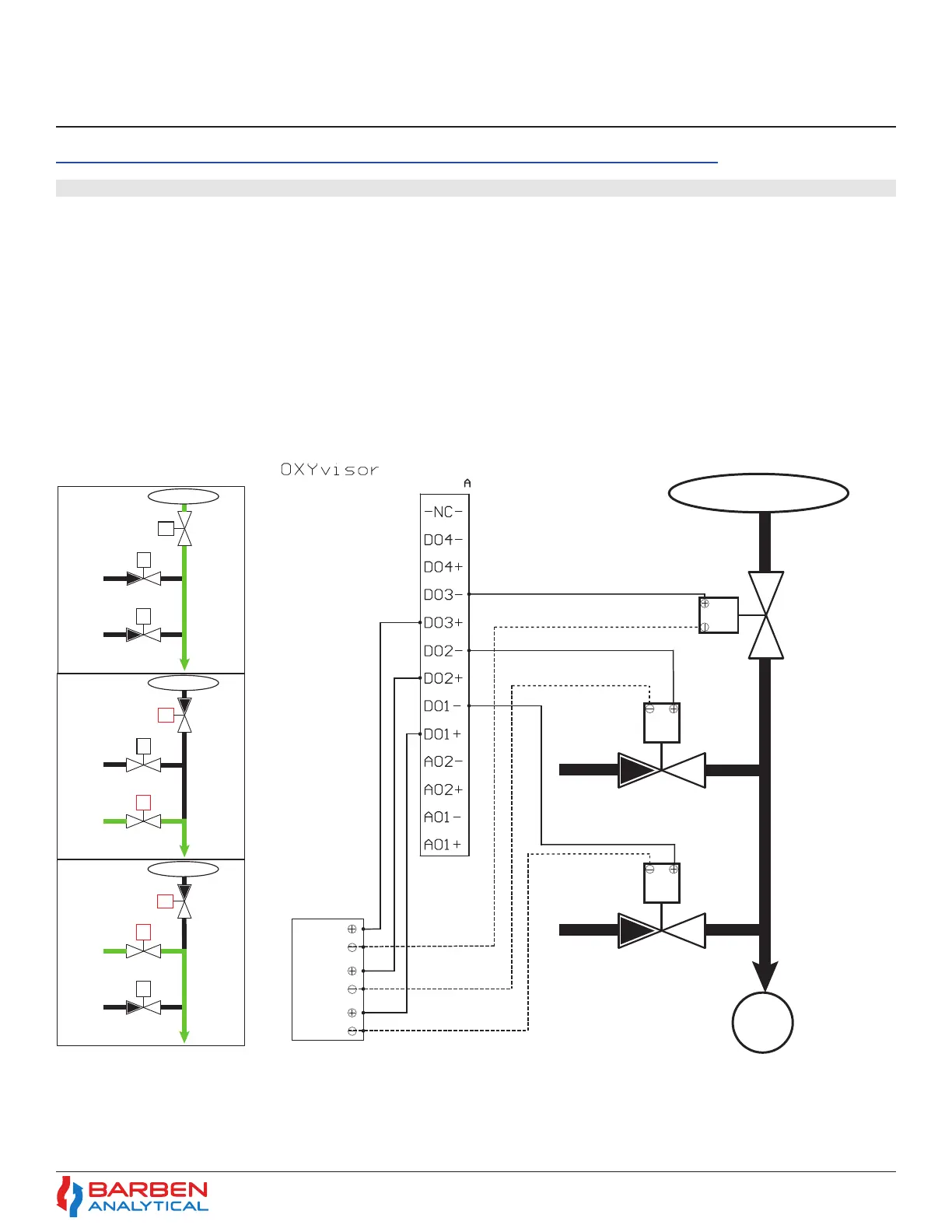
To setup the OXYvisor for Auto-Calibration (AutoCal) there are some additional hardware requirements.
• (QTY 3) Low-Watt Solenoid Valves to operate the Auto-calibration panel. One solenoid for the process isolation valve
and two for the calibration gases, zero and span.
• External Power Supply with proper Area Classication to power the solenoids. The OXYvisor has non-powered on/o
digital relays to control the AutoCal routine.
The AutoCal setup can be setup via the HMI, however it is fairly tedious and it is recommended to use the OXYvisor
OxygenAnalyzer software provided with the analyzer to set up this routine. Refer to the OXYvisor Software Instruction
Manual for detailed setup instructions.
Terminal
S
S
S
24 V
24 V
24 V
Customer Supplied
Process Sample Gas Inlet
DO3 - Process
Solenoid
Normally Open
DO2 - Span Gas Solenoid
Normally Closed
DO1 - Zero Gas Solenoid
Normally Closed
(Supplied Seperately)
(Supplied Seperately)
(Supplied Seperately)
S
S
S
Process Sample Gas Inlet
DO3 - Process
Solenoid
Normally Open
DO2 - Span Gas Solenoid
Normally Closed
DO1 - Zero Gas Solenoid
Normally Closed
Normal
Operation
S
S
S
S
S
Process Sample Gas Inlet
DO3 - Process
Solenoid
ACTIVE - CLOSED
DO2 - Span Gas Solenoid
Normally Closed
DO1 - Zero Gas Solenoid
ACTIVE - OPEN
Cal Zero
Operation
S
Process Sample Gas Inlet
DO3 - Process
Solenoid
ACTIVE - CLOSED
DO2 - Span Gas Solenoid
ACTIVE - OPEN
DO1 - Zero Gas Solenoid
Normally Closed
Cal Span
Operation
DO1 - NORMAL - CLOSED
DO2 - NORMAL - CLOSED
DO3 - NORMAL - OPEN
DO1 - ACTIVE - OPEN
DO2 - NORMAL - CLOSED
DO3 - ACTIVE - CLOSED
DO1 - NORMAL - CLOSED
DO2 - ACTIVE - OPEN
DO3 - ACTIVE - CLOSED
O
Sensor
Figure A.4. 38 - AutoCal General Arrangement & Wiring