29
Installation, Operation & Maintenance Manual
OXYvisor Optical Oxygen Analyzer
The OXYvisor can be ordered with either 120-
240VAC input power or 24VDC input power.
Before connecting any electrical signal or power, a
protective ground on the analyzer enclosure must be
connected. Requirements for the Protective Ground
conductor are as follows:
• The protective conductor must be of equal or
greater size than any other current-carrying
wiring.
• The protective conductor must remain connected
until all other wiring is removed.
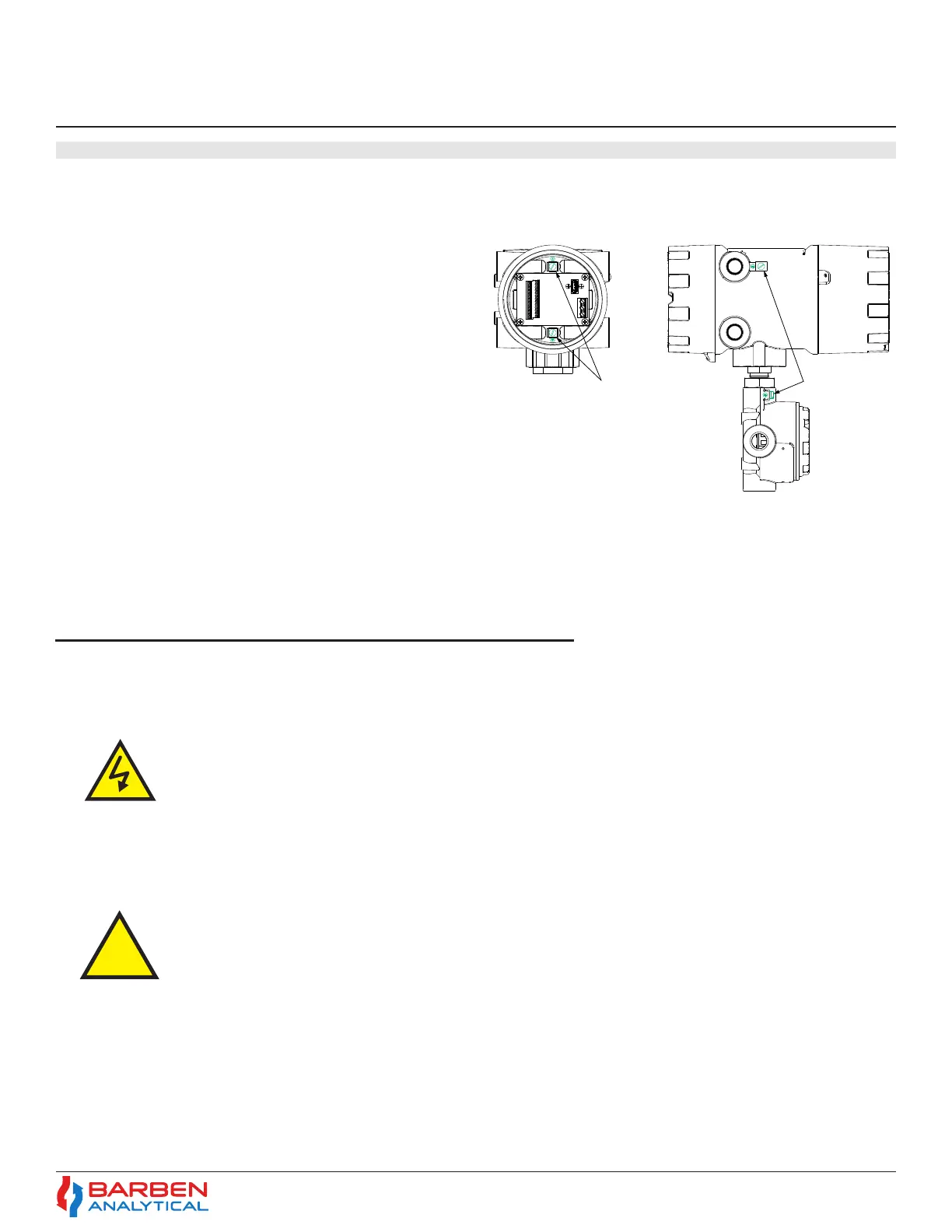
Figure (12) shows the Protective Ground screw
locations.
AC Power
OXYvisor analyzers ordered with AC power input will have a termination board labeled with “Line”, “Neutral”,
and “Earth” (Ground) as shown in Figure (9).
Warning - Hazardous voltage and risk of electrical shock - make sure main power is shut o
prior to attaching wiring to analyzer.
Power Supply wiring requirements:
• 24 to 12 gauge (IEC .500 to 2.00)
• Copper, stranded wire
• Minimum 300V Insulation
• Tightened (torque) to 0.5 to 0.6 Nm
4�6 Wiring - Power
4�6�2 AC Powered Analyzer
4.6.1 Protecve Ground (Earthing) Screw
The OXYvisor control unit can operate using between 85-264 volts AC, 47 to 63 Hz. There is no power switch
or circuit breaker on the control unit, and it must be protected by installing it on a circuit-protected line, with
recommended maximum 1 amperes, with a switch or circuit breaker in close proximity to the control unit and
within easy reach of an operator. Mark the switch or circuit breaker as the control unit disconnecting device.
Figure 12 - OXYvisor Protective Ground Screws
Analyzer Side ViewAnalyzer Rear View
(Rear Lid Removed)
Internal Protective
Ground Screws
Ground Screws
Section 4
Installation
Analyzer- Mains Supply Connections (AC Version)