30
Installation, Operation and Maintenance Manual
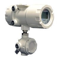
OXYvisor Optical Oxygen Analyzer
Input /Output wiring requirements:
• 26 to 16 gauge (IEC .400 to 1.25)
• Copper, stranded wire
• Minimum 300V Insulation
• Tightened (torque) to .22 to .25 Nm
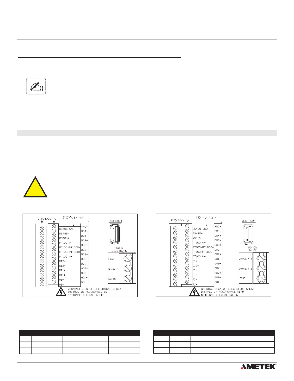
Input / Output Wiring
All Input / Output wiring for the OXYvisor analyzer is located on the left side of the board as shown in Figure (9)
and (10). The wiring assignments are shown in Table (1).
Please note that the 24VDC version of the analyzer is a 4-wire device. It has
separate wiring for power and signal (not a loop powered device).
4�6�3 DC Powered Analyzer
DC Power
OXYvisor analyzers ordered with DC power input will have a termination board labeled with “24VDC (+)”,
“24VDC (-)”, and “Earth” (Ground) as shown in Figure (10).
Analyzer - Power Supply Connections (DC Version)
The OXYvisor control unit can operate using 24 VDC +/-10%. When energized by mains the 24 V DC supply
must be from a Class2 or LPS source, OR that a fuse (1 A) will be required in the installation.
4�7 Wiring - Input/Outputs
Label Terminal Description Function
Line Power 120/240VAC 85-264 VAC 47/63Hz Input Power Line Power wiring
Neutral Power 120/240VAC 85-264 VAC 47/63Hz Input Power Neutral Power Wiring
Earth Power 120/240VAC Earth Terminal Earth Terminal
Label Terminal Description Function
24VDC (+) Power 24VDC 21.6 - 26.4 VDC Positive DC Power wiring
24VDC (-) Power 24VDC 21.6 - 26.4 VDC Negative DC Power Wiring
Earth Power 24VDC Earth Terminal Earth Terminal
AC TERMINAL BOARD POWER WIRING DC TERMINAL BOARD POWER WIRING
Terminal
Terminal
Terminal
Terminal
Figure 13 - AC Terminal Board - Located in Rear (Wiring) Compartment Figure 14 - DC Terminal Board - Located in Rear (Wiring) Compartment
Section 4
Installation