31
Installation, Operation & Maintenance Manual
OXYvisor Optical Oxygen Analyzer
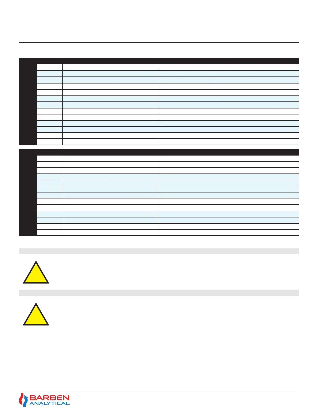
Input / Output
TERMINAL - B
Label Description Function
RS485 GND Serial Communication Modbus RS485 RTU Common Wire
RS485 - Serial Communication Modbus RS485 RTU Data Negative Wire
RS485 + Serial Communication Modbus RS485 RTU Data Positive Wire
PT100 V - PT1000 4-wire or jumper to next terminal PT100 4 wire RTD input, Drive Voltage negative wire (black)
PT100/PT1000 - PT1000 Temperature Sensor PT1000 negative wire then jumper to PT100 - terminal above
PT100/PT1000 + PT1000 Temperature Sensor PT1000 positive wire then jumper to PT100 + terminal below
PT100 V+ PT1000 4-wire, 3’rd wire or jumper to above terminal PT100 4 wire RTD input, Drive Voltage positive wire (red)
DI2 - Digital Input 2 (0 VDC) Powered Digital input, Negative Wire, Connect to external switch for remote Test Gas Insert
DI2 + Digital Input 2 (5 VDC) Powered Digital input, Positive Wire, Connect to external switch for remote Test Gas Insert
DI1 - Digital Input 1 (0 VDC) Powered Digital input, Negative Wire, Connect to external switch for remote AutoCal Initiation
DI1 + Digital Input 1 (5 VDC) Powered Digital input, Positive Wire, Connect to external switch for remote AutoCal Initiation
AI1 - Analog Input (0 VDC, 4-20mA) Analog Input, Negative Wire, 24VDC Powered,. Programmable for Temperature or Pressure
AI1 + Analog Input (24 VDC, 4-20mA) Analog Input, Positive Wire, 24VDC Powered,. Programmable for Temperature or Pressure
Input / Output
TERMINAL - A
Label Description Function
-NC- Not used Not used
DO4 - Relay Output 4 (24VDC, 0.05A pilot duty, 0.4A resistive load) Programmable, Isolated Relay Negative wire
DO4 + Relay Output 4 (24VDC, 0.05A pilot duty, 0.4A resistive load) Programmable, Isolated Relay Positive wire
DO3 - Relay Output 3 (24VDC, 0.05A pilot duty, 0.4A resistive load) Programmable, Isolated Relay Negative wire, (Process Gas Relay if AutoCal is used)
DO3 + Relay Output 3 (24VDC, 0.05A pilot duty, 0.4A resistive load) Programmable, Isolated Relay Positive wire, (Process Gas Relay if AutoCal is used)
DO2 - Relay Output 2 (24VDC, 0.05A pilot duty, 0.4A resistive load) Programmable, Isolated Relay Negative wire, (Span Cal Relay if AutoCal is used)
DO2 + Relay Output 2 (24VDC, 0.05A pilot duty, 0.4A resistive load) Programmable, Isolated Relay Positive wire, (Span Cal Relay if AutoCal is used)
DO1 - Relay Output 1 (24VDC, 0.05A pilot duty, 0.4A resistive load) Programmable, Isolated Relay Negative wire, (Zero Cal Relay if AutoCal is used)
DO1 + Relay Output 1 (24VDC, 0.05A pilot duty, 0.4A resistive load) Programmable, Isolated Relay Positive wire, (Zero Cal Relay if AutoCal is used)
AO2 - Analog Output 2 (4-20mA) Active Analog Output (Negative wire, Active 24 VDC)
AO2 + Analog Output 2 (4-20mA) Active Analog Output (Positive wire, Active 24 VDC)
AO1 - Analog Output 1 (4-20mA) Active Analog Output (Negative wire, Active 24 VDC)
AO1 + Analog Output 1 (4-20mA) Active Analog Output (Positive wire, Active 24 VDC)
INPUT / OUTPUT WIRING
Unused entries shall be closed with suitable certied Ex db blanking elements with a minimum
IP66 rating
After wiring the power and any input / output connections and before powering up the analyzer,
the Rear (Wiring) Compartment lid should be installed and fully tightened. Follow the detailed
instruction found in Section 6.4.1.
4.8 Electrical Entries
4.9 Securing the Rear (Wiring) Compartment lid.
Section 4
Installation