77
Installation, Operation & Maintenance Manual
OXYvisor Optical Oxygen Analyzer
To interrogate process variables such as oxygen, pressure, temperature, phase, amplitude, etc. refer to Table
3 for Base Addresses, then implement the oset, function code and choose data type as shown in the example
below. For basic Modbus RTU conguration settings, refer to Table 1.
The 4 relays in OXYvisor can be activated one at a time manually. Follow the steps below to specify, start and
stop individual relays. Until one relay is not deactivated, the other relay cannot be written to.
1. Set the relay test number (Register Address : 44010). The values can be set to 1 , 2 , 3 or 4 for the
corresponding relay.
2. Set the relay test position (Register Address : 44011). The value can be set to 0 to OPEN and 1 to
CLOSE the relay. (Note: The relay will not open or close unit you activate it in the next step.)
3. Activate the relay status (Register Address : 44012). To activate, set the relay status value to (0X01).
4. To deactivate the relay set the relay status (Register Address : 44012) to (0x02).
A7.4 - Communicaon Guide
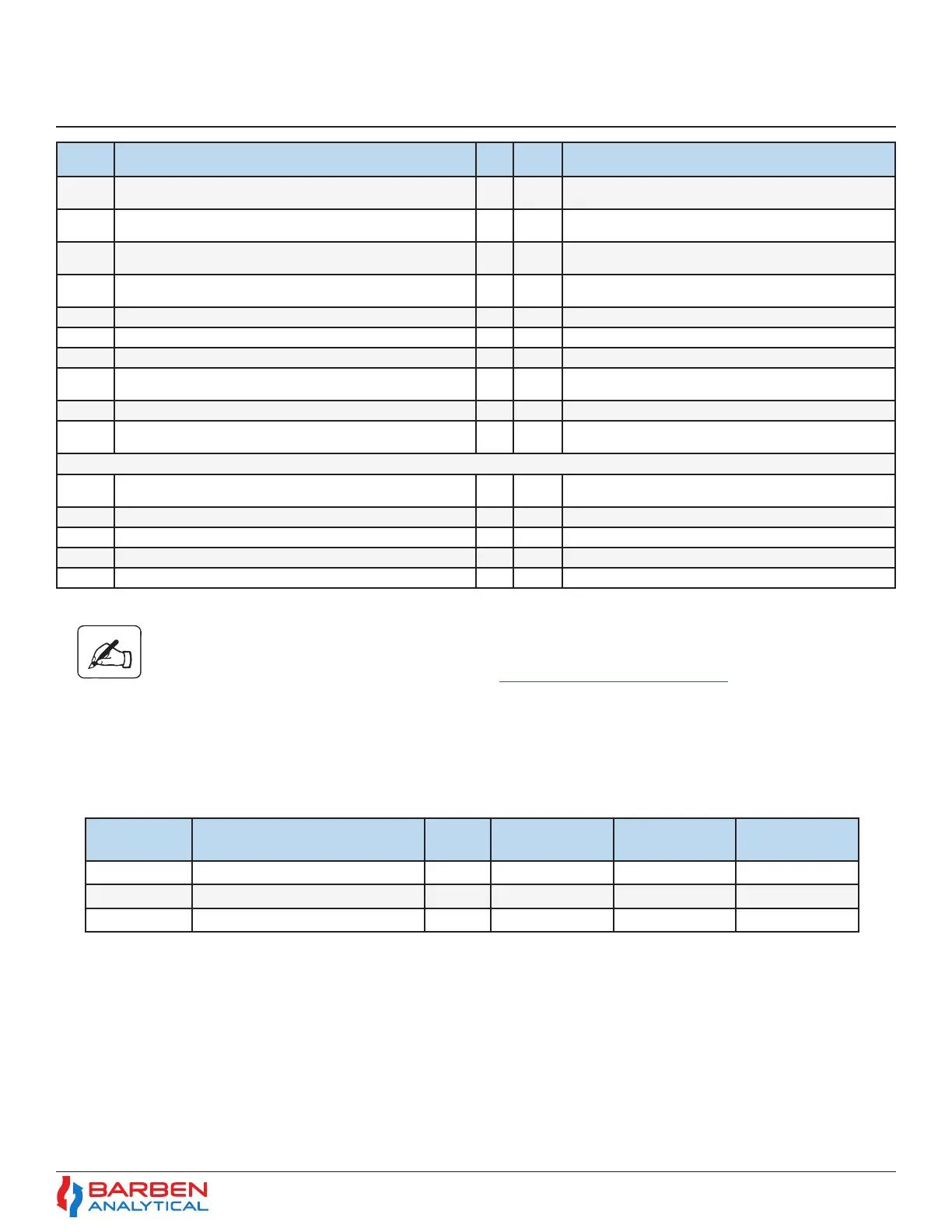
A7.4.1 Reading Process Variables:
A7.4.2 Turning on Relays
PROCESS
VARIABLE
FIRST REGISTER MINUS
OFFSET
FUNCTION CODE DATA TYPE RESULT
(EXAMPLE)
Oxygen 30002 30000 4
Float 20.97
Amplitude 30006 30000 4
Uint32 14671
Temperature 30022 30000 4
Float 69.89
Note: The “minus oset” should be 40000 for all the above read/write only registers.
*Addresses which are 4bytes long, needs 2 registers updated at once and function code 16 must be used.
** Current UTC time in seconds can be found on https://www.epochconverter.com/
Base
Address
Register Name Size Type
40160 congVar.CalibrationCongVars.autoO2SenCal.
calibrationFrequency[2].rstCalibrationTime
4* uint32 Current time (UTC**) value in seconds +time delay
(seconds)
40162 congVar.CalibrationCongVars.autoO2SenCal.
calibrationFrequency[3].calibrationIntervalActivated
2 uint16 0x01 = enable; 0x02 = disable
40168 congVar.CalibrationCongVars.autoO2SenCal.
calibrationFrequency[3].calibrationInterval
4* uint32 0 - 5184000 (in seconds)
40170 congVar.CalibrationCongVars.autoO2SenCal.
calibrationFrequency[3].rstCalibrationTime
4* uint32 Current time (UTC**) value in seconds +time delay
(seconds)
40185 congVar.CalibrationCongVars.autoO2SenCal.zeroPurgeTime 4* oat 1-30 (in minutes)
40187 congVar.CalibrationCongVars.autoO2SenCal.spanPurgeTime 4* oat 1-30 (in minutes)
40189 congVar.CalibrationCongVars.autoO2SenCal.recoveryTime 2 uint16 1-120 (in seconds)
40408 congVar.DiagAndTestCongVars.testGasInsert.
timePeriodForTestGas
4* oat 1-100 (in minutes)
40410 congVar.DiagAndTestCongVars.testGasInsert.outputDene 2 uint16 0x01 = Zero Gas; 0x02 = Span Gas
44000 calibrationStateWriteRegister 2 uint16 0X04 = Start Auto Calibration; 0X05 = Stop Auto
Calibration
RAM Locations
44000 calibrationStateWriteRegister 2 uint16 0X04 = Start Auto Calibration; 0X05 = Stop Auto
Calibration
44009 testGasInsertStatus 2 uint16 0x01 = start test gas insert, 0x02 = stop test gas insert
44010 relayTestNumberStatus 2 uint16 1,2,3 and 4 for the corresponding relay
44011 relayTestPositionStatus 2 uint16 0 - open and 1 - close
44012 relayTestStatus 2 uint16 1- Activate and 2 - deactivate