A-6 | Thermox WDG-V Series Analyzers
Auto Calibration is not a standard feature of the WDG-V Analyzer.
Do not select Auto Calibration unless your analyzer is equipped with
a Remote Calibration Unit (RCU).
Figure 4. HOME screen with Combustibles and Methane options activated.
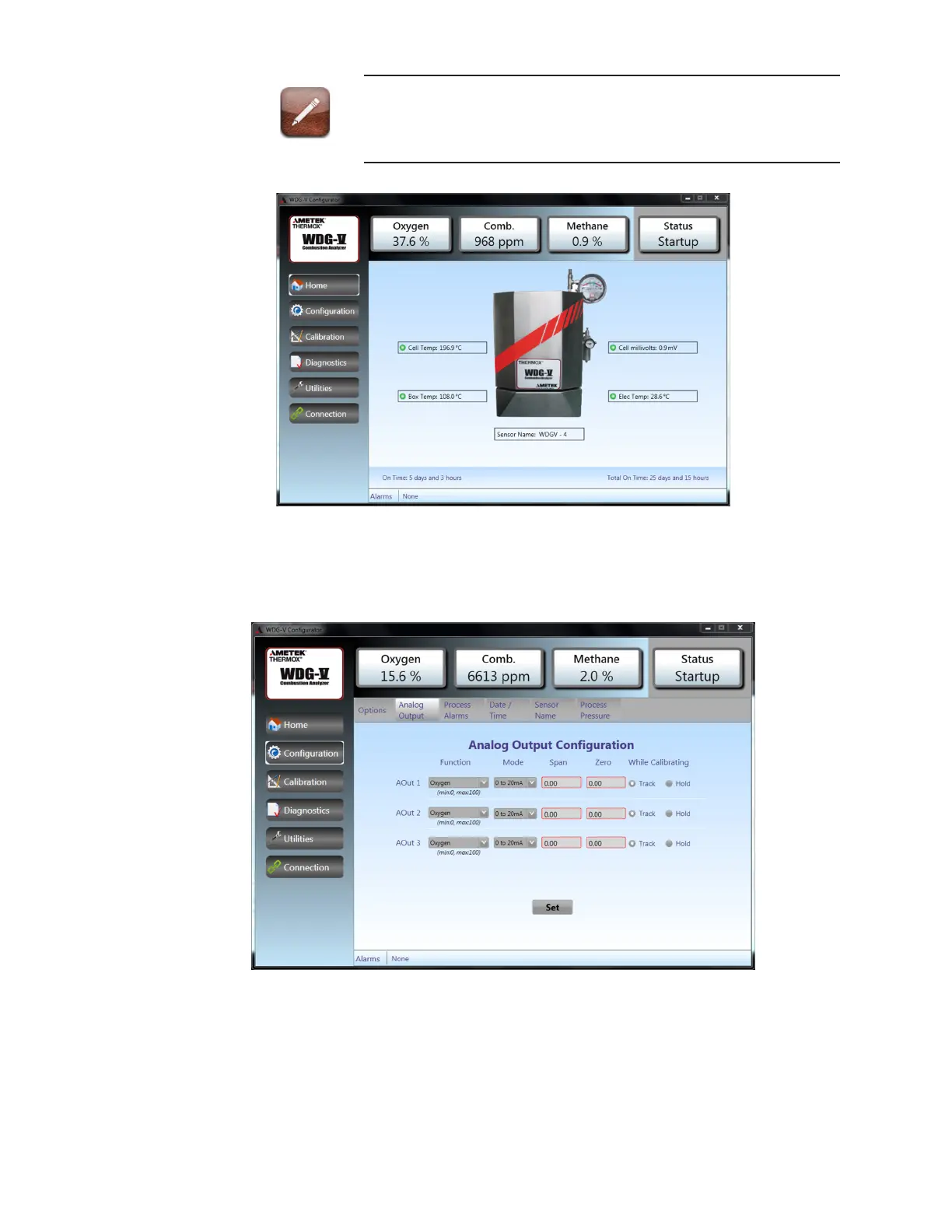
Conguration_AnalogOutput
Figure5.Conguration_AnalogOutputscreen.
 Loading...


