Page 96
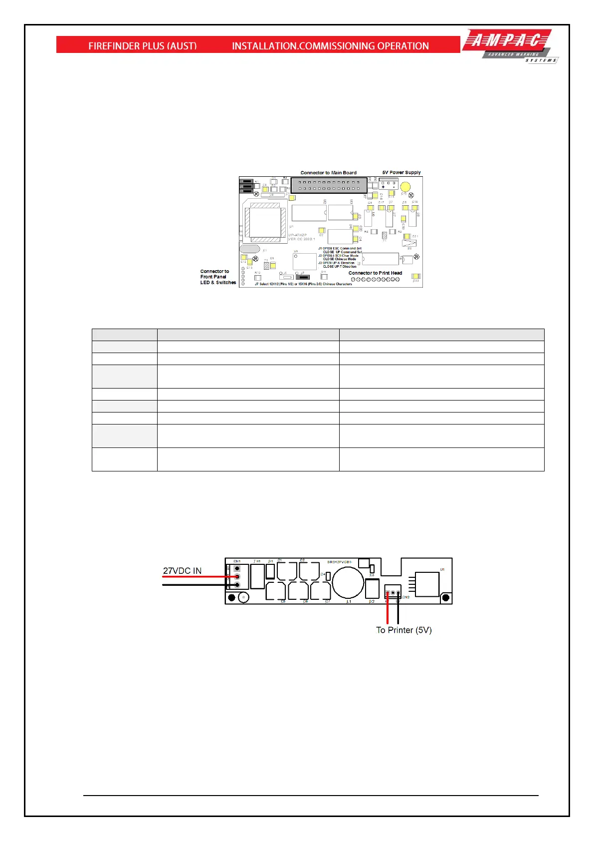
12.18.3 Printer Connections and Jumpering
Mounted on the back of the printer mechanism is the PCB that carries the;
➢ Connectors for interconnection to the Main Board,
➢ Jumper links required to set the programmed print modes; and
➢ Printer 5 volt DC Power Supply.
Figure 121: PCB Layout
Jumper Settings
Selects ASCII Character Printing Mode
Selects Chinese Character Printing Mode
Select Printing by Contrary Direction
Select printing in the Normal Direction
Insert the Shorting Clip Between Pins
1 and 2
Insert the Shorting Clip Between Pin 2
and 3
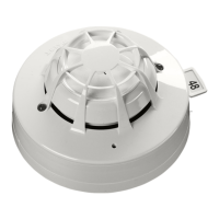
12.18.4 Printer 5 Volt Power Supply
27 volts DC is taken from Main Board (BRD86MBA) and fed to CN1 of the 5volt Printer Power Supply
Board. It is this board that drops this voltage from 27volts to 5volts for use by the Printer. Mounted to
rear of printer
Figure 122: Printer Power Supply Board Layout