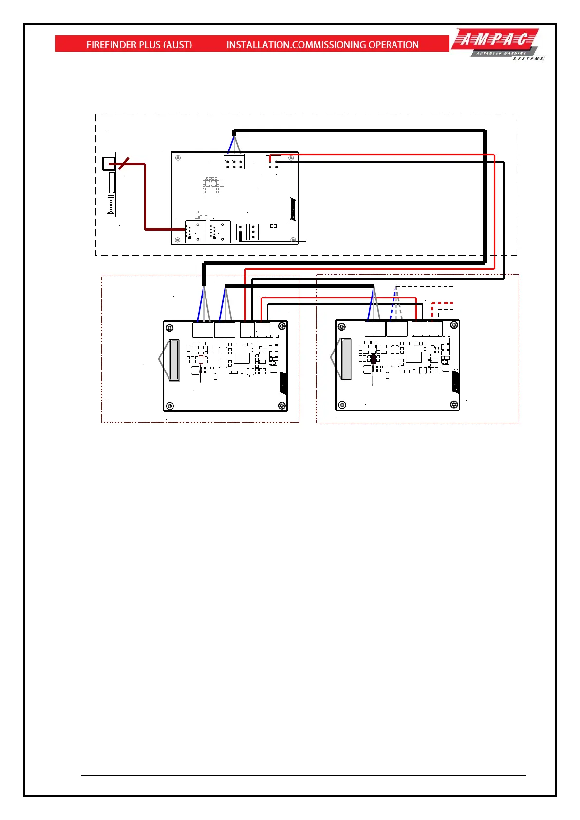
Figure 101: Connecting SmartTerminal’s to the FACP
12.15.4 Setting the SmartTerminal Address
Open the front door; locate the “CONFIG” button situated on the left hand side of the PCB and press
for 3 seconds. The buzzer and “Config” LED will double beep and flash respectively to indicate that the
Configuration mode has been entered.
The LCD will now display the Configuration screen. This screen consists of the code version number,
current address and four adjustment markers. These markers A-, A+, C-, and C+ are used to indicate
the buttons that adjust the address and LCD contrast.
Use the “PREVIOUS (A-) and NEXT” (A+) buttons to select the desired address. The default value for
this address is 255 which is not a valid SmartTerminal address. The user must then select an address
value from 1 to 30, i.e. the same address as that set in the FACP. The buttons corresponding to C-
(SILENCE BUZZER) and C+ (RESET) are used in a similar manner to decrease and increase the
LCD contrast level. There is audible feedback for all button presses.
Once the address has been set press the “CONFIG” button again for 3 seconds and the screen will
return to its default and the “DIAGNOSTIC” LED will return to a slow flash. This slow flash indicates
SmartTerminal and the FACP are communicating normally i.e. the LED flashes if communications
data is being received from the FACP.
Note: If the address is not set within the time out period of approximately 75 seconds
SmartTerminal will return to its previous state.