Page 16
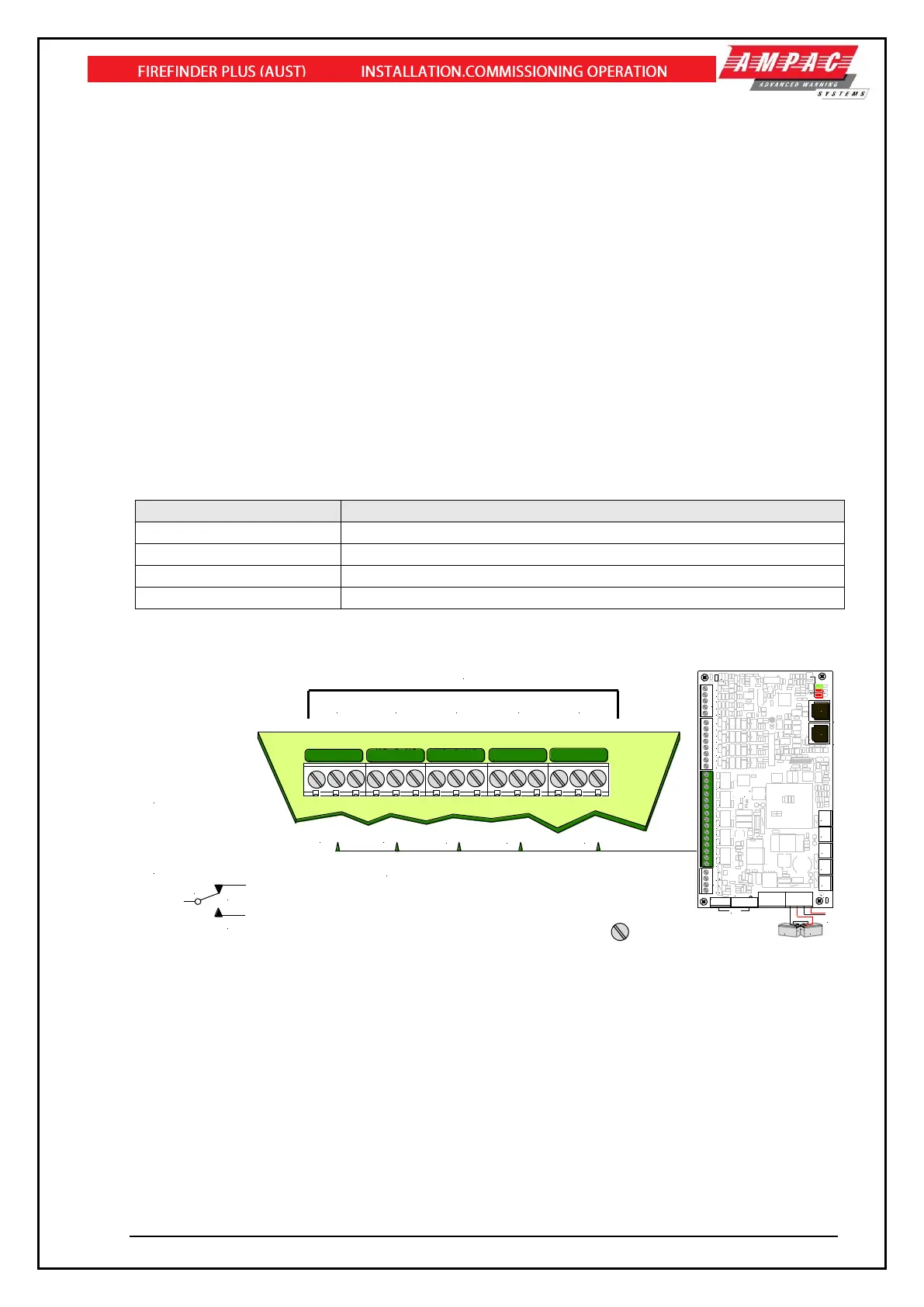
4.8.5 Relay Output Connections
Five “voltage free” relay outputs (TB2 – TB6) are provided and can be configured for a variety of uses.
➢ Alarm - activated on device alarm conditions and “Function” programmed logics. The relay
is turned off during a ALARM disable condition.
➢ Sprinkler - activated on device alarm conditions and “Function” programmed logics.
➢ Fault - activated on all fault conditions and “Function” programmed logics. The relay is
turned off during a FAULT disable condition.
➢ Isolate - activated on all isolate conditions and “Function” programmed logics.
➢ Battery Fail - activated on battery fail conditions and “Function” programmed logics.
➢ Mains Fail - activated on a mains power fail condition and “Function” programmed logics.
➢ Warning System - activated on evacuation, device alarm conditions and “Function”
programmed logics. If the activation of this relay is due to an evacuation condition, then the
relay is turned off during an Alarm (sounder) disable or Alarm (sounder) silence condition.
➢ Ancillary - activated on device alarm conditions.
➢ General Purpose - activated via “Function” programmed logics
Relay Switching Characteristics
These outputs have been designed to be able to switch predominately resistive loads as listed below.
TB2
TB3
TB4
TB5
TB6
TB2 to TB6 are located on the
lower to mid left hand side of the board
C
NC
NO
1A Un-monitored
Voltage Free Conacts:
NO: Normally Open
NC: Normally Closed
C: Common
NO C NC
NO C NCNO C NC
NO C NC
NO C NC
NO C NC
NO C NC
Note:
NO C NC
NO C NC
FIRE
FAULT
EWIS
ISOLATE
BATT
FAIL
Relays are Programmable. Default Setup Shown
+27VDC
from PSU
Battery 2
12Volts
Battery 1
12 Volts
+
-
-
+
HPCI
POWE R OK
22/09/09
SGD
AUX OUT 1 AU X OUT 2
+
-
N/CCN /O N/C
C
N/O
1+ 1- 2+ 2- 3+ 3- 4+ 4- 2+ 3+ 4+
C
JTAG
E. BOARD CONTROL
CO MMS .
CO MMS .
ET H
BAT+
BAT-
+27V
0V
COMMS FAIL
EOL
1+
E. BOARD SW. POWER
BRD86BPSC4 -
EXT TEMP
L9
R103
R108
C36
C34
C35
C56
C58
CN4
CN5
CN6
CN7
CN11
CN10
CN2
D9
D10
D11
D7
LK1
M2
M11
M1
M4
M12
M3
M6
M13
M5
M8
M14
M7
M10
M15
M9
Q5
R75
RL1
RL2 RL3 RL4
RL5
TB2
TB3
TB5
TH4
TH2
TH1
TH7 TH8
U2
U8
U5
U6
U7
ZD8
ZD5
ZD4
ZD1
ZD6
ZD2
ZD7
ZD3
TB10
HSNK2
CN3
N1236
L6
L7
L8
C43
CN12
1
T1
Q8
TH5
HSNK1
TH9
CN8
M16
CN 10
RS 485
CO MMS.
IN
CN 11
RS 485
CO MMS.
OU T
RELAY 4
RELAY 5
MON ITOR ED OUTP UTS
N/CCN /O
N/CCN /ON /CCN/O
RELAY 3
RELAY 2
RELAY 1
+
-
POW ER
O/Ps
BATT
FLT.
MON EN
MON ITORED INPUT S
BRIGADE
BOARD
CN1
TB1
TB8
TB7
TB4
TB6