Page 14
4.8.3 Monitored Inputs
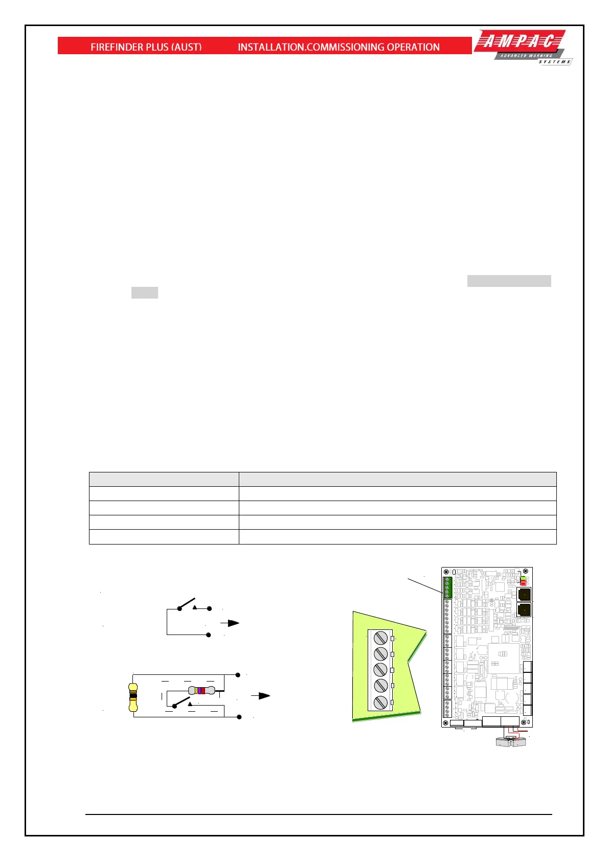
Four independently monitored inputs (TB8) are provided and can be configured for a variety of uses.
➢ Manual Call Point (MCP) – if activated the FACP will go into alarm. Connected to the MCP
on the front of the FACP.
➢ Class Change – if activated all Alarm Devices/Sounders and Alarm Device/Sounder
Outputs in Sounder Group 1 are turned on.
➢ External Fault – if activated the FACP will indicate a Fault condition
➢ Ancillary Disable - if activated, the FACP’s “DISABLED” and ANC OUTPUT STATUS LEDs
will both be turned on. Note that this event is used to indicate an ancillary/auxiliary
disablement or a door-opened condition if a door switch is fitted. It also activates any Relays
on the Brigade board configured as “Isolate” relays and affects the Brigade Board’s
“Aux/Anc” outputs based on their “normally energised” settings.
➢ Evacuate – if activated the FACP goes into Evacuation.
➢ Sounder Silence – if activated all activated sounders are silenced.
➢ Reset – if activated a Master Reset is initiated.
➢ Fire/Feedback - if activated, the FACP’s “Fire Output On” LED will flash (AS7240.2 Clause
7.9.2). Note that this is a latched condition and will only be cleared a “Master Reset”
command from the FACP.
➢ General Purpose – for use in Functions (Cause and Effects)
The default configuration types for the inputs are as follows:
• Input 1 – MCP
• Input 2 – Evacuate
• Input 3 – External Fault
• Input 4 – Reset
The inputs have been designed to operate with a programmable EOL of 3K3Ω, 10KΩ 22KΩ or
Unmonitored (no EOL) the 10K EOL is the default. The normal and active ranges change according to
the end of line selected.