SECTION 6 – TEST AND PLACE IN SERVICE
2014-MAY-01 REV. 01 PAGE 6-15
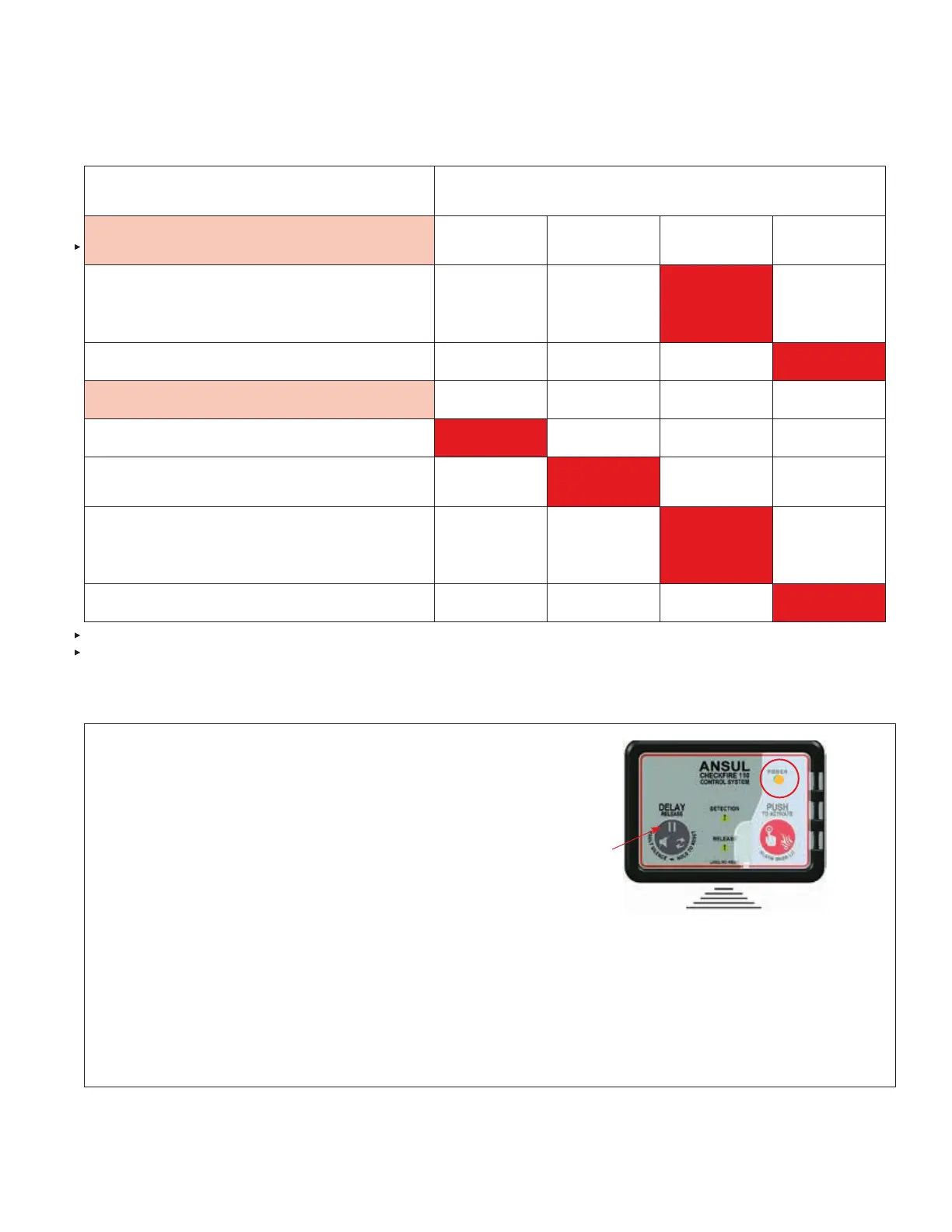
CHECKFIRE 110
Detection and Actuation System
“PUSH To Activate / Alarm When Lit” LED
and Sounder Indications
Manual Action
(Release Circuit Activation)
2 x 1 sec.
for 10 sec.
4 x 1 sec.
for 5 sec.
Steady-on
for 10 sec.
1 x 10 sec.
until reset*
Push the “PUSH to Activate / Alarm When Lit” button
Or: Pull ring pin and push an EMA
(Immediate release for either action)
Post discharge
Detection Circuit Input
15-Second Time Delay (1st 10 seconds)
5-Second Time Delay
And 5 Seconds to release for 15 Second Time Delay
Release Circuit Activation
(Time Delay Expired)
Post discharge
TABLE 6-5: SUMMARY ALARM CONDITION INDICATORS
Disconnect external power circuit connection at the
CHECKFIRE 110 Power Circuit Lead.
1. Power LED pulses AMBER 1 x 30 seconds.
2. Sounder pulses 1 x 30 seconds for 10 minutes then
auto-silences to conserve energy. Do not wait for auto-si-
lence to begin, move to next step.
3. Push the “DELAY/Reset/Silence” button to test Sounder
silence. The LED continues to pulse 1 x 30 seconds.
4. Repeat the following tests (pages 6-9 thru 6-13) with
control module on internal power:
Note: For above tests the Power LED continues to pulse
AMBER 1 x 30 seconds.
TABLE 6-6: INTERNAL POWER CIRCUIT – OPERATIONAL TEST
009180b
INTERNAL POWER
TESTING (REMOVE
POWER CABLE)
AMBER POWER
LED AND
SOUNDER PULSE
1 X 30 SECONDS
PUSH TO SILENCE
SOUNDER (LED
CONTINUES)
REPEAT TESTS
ON INTERNAL
POWER
* Release Fault Indicator also pulses at this rate during post discharge. When release circuit test device is installed,
Release Fault Indicator does not pulse.